
Lecture
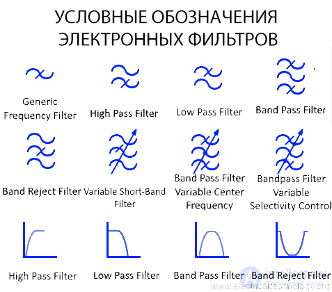
Electronic filters are used to control the frequency spectrum of a signal. The following schematic symbols are used in circuits for various types of filters:
Low-Pass Filter (LPF):
High-Pass Filter (HPF):
Band-Pass Filter (BPF):
Band-Stop Filter (or Band-Reject Filter, BSF):
Active Filters:
Filters with Adjustable Frequency Response:
Universal Frequency Filter

This is a general symbol representing a frequency filter. A frequency filter is an electronic circuit that rejects or attenuates certain frequencies and passes others. This symbol represents only a frequency filter in general, not a specific type.
High-Pass Filter
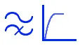
This type of filter passes only high-frequency signals and blocks or attenuates low-frequency signals; it is called a high-pass filter.
The symbol depicts two waves (signals), i.e. a lower and an upper signal, corresponding to low and high frequency respectively. The lower dashed signal represents the blocked low frequency.
Low-Pass Filter
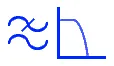
A low-pass filter blocks or attenuates any high-frequency signal and passes a low-frequency signal; it is called a low-pass filter. The symbol denotes the blocked high frequency.
Band-Pass Filter
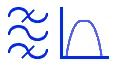
A band-pass filter blocks both low and high frequencies but passes frequencies between the low and high frequency. The allowed frequency range forms a band, hence the name band-pass filter. The symbol shows that the upper and lower signals are shaded (blocked), while the signal between them passes through.
Band-Stop Filter
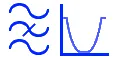
A band-stop filter, or notch filter, is also known as a rejection filter. As its name suggests, this filter blocks or rejects a specific band of frequencies. Frequencies above or below this specific band pass through without any attenuation.
Variable Notch Filter

This is a type of notch filter with a variable frequency range. The rejected frequency band can be changed using a special feature, usually a knob, that alters the values of the components within the circuit.
Band-Pass Filter with Variable Center Frequency

This is a type of band-pass filter with a variable center frequency. The center frequency is the midpoint between the lower and upper corner frequencies. Changing the center frequency changes the filter's band.
Band-Pass Filter with Adjustable Selectivity

This type of band-pass filter has variable selectivity, which allows the filter to change the allowed frequency band by changing the corner frequencies.
Below is a list of the electronic filter symbols explained above.

Comments