
Lecture
In every electrical circuit you have to switch devices and equipment on and off. Switching devices are used for this purpose, which can range from a simple switch or knife switch to relays, contactors, and so on. Today we will look at one such device — the solid state relay. Let's talk about what it is, how to choose one, and how to connect it into a load control circuit.
A solid state relay (SSR) is an electronic device that is a type of relay without mechanical moving parts, used to switch a high-power circuit on and off by means of low voltages applied to the control terminals. An SSR contains a sensor that responds to an input (control signal) and solid-state electronics that switch the high-power circuit. This type of relay can be used in both DC and AC networks. The device performs the same functions as a conventional relay, but contains no moving parts. A solid state relay is a device built on semiconductor elements and power switches such as triacs, bipolar transistors, or MOSFETs. In English-language sources, solid state relays are called SSR, from Solid State Relay (which is a literal equivalent of the Russian name). In fact, these are a triac and an optocoupler in a single housing.
Like electromagnetic relays and other switching devices, they are designed to control a load with a higher voltage or current using a weak signal.
Differences between solid state and electromagnetic relays
A conventional relay, like all electromagnetic switching devices, works as follows: there is a coil to which current is supplied from a control system or a push-button station. As current flows through the coil, a magnetic field arises that attracts the armature together with the contact group. The contacts then close, and current begins to flow through them to the load.
Solid state relays have no control coil and no moving contact group. What is inside a solid state relay you can see below. As mentioned above, instead of power contacts it uses semiconductor switches — transistors, triacs, thyristors, and others, depending on the application (right side of the photo).
Commercially produced solid state relays use semiconductor device technologies, such as thyristors and transistors, to switch currents up to hundreds of amperes. SSRs have a higher switching speed than electromechanical relays and provide full galvanic isolation. Solid state relays are less capable of withstanding brief overloads (exceeding the maximum permissible currents and voltages) than their electromechanical counterparts, and they have a slightly higher resistance in the closed state.
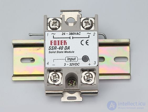
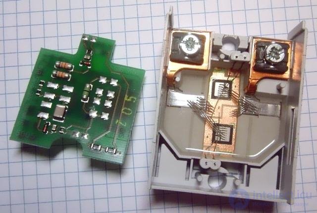
This is the main difference between a semiconductor relay and an electromagnetic one. Because of this, a solid state relay has a much longer service life, since there is no mechanical wear of the contact group, and it should also be noted that the switching speed of semiconductor relays is higher than that of electromagnetic ones.
Besides the absence of mechanical wear, there are also no sparks or arcs during switching, and no sound from contacts striking each other when switching. Incidentally, since there are no sparks or arc discharges during switching, solid state relays can operate in explosion-hazard areas.
The following table gives the general specifications of solid state relays of the TSR (three-phase) and SSR (single-phase) series from the manufacturer "FOTEK" (incidentally, among the most widespread). In general, other manufacturers' products will have similar or identical specifications.
| Insulation resistance | >50 MΩ / 500V DC |
| Input/output insulation dielectric strength | Withstands 2.5 kV AC for 1 minute |
| Trigger current | No more than 7.5 mA |
| Overload capacity | Up to 10 rated currents for 10 ms |
| Switching method | At zero crossing (in AC models) or instantaneously via optocoupler (for DC) |
| Built-in protection | The SSR-F series has a replaceable fuse |
Types and classification
There are several ways to classify relays. You may come across more or less detailed explanations of such classifications. We will not go into detail here, since more detailed descriptions can easily be found in the relevant textbooks and reference manuals.
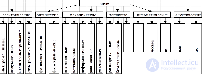
A solid state relay can be classified:
By current type (DC or AC);
By current rating (low-power, power);
By mounting method;
By voltage;
By number of phases;
By type of control signal (DC or AC current, analog input for control via a variable resistor, a 4-20 mA loop, etc.).
By switching type — switching at zero voltage crossing (in AC circuits), or switching according to the control signal (for power regulation, for example).
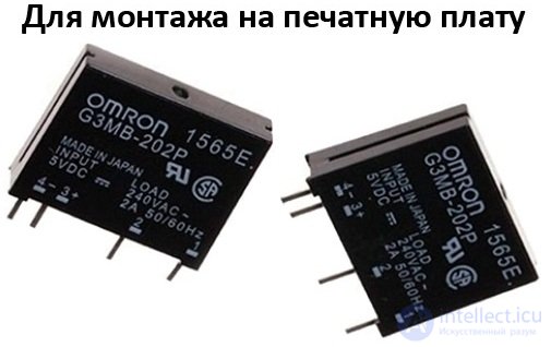
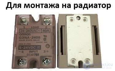
So, by number of phases there are single-phase and three-phase relays. But there are far more types of control signals. Depending on the internal design, solid state relays can be controlled by either DC or AC voltage.
The most common solid state relays are those controlled by a DC voltage in the range of 3 to 32 volts. In this case, the controlling voltage value only needs to fall within this range, rather than equal some specific value within it, which is very convenient when integrating into systems with different voltages.
There are also semiconductor relays controlled by an analog signal:
4-20 mA;
0-10 volts DC;
A variable resistor of 470-560 kΩ.
With such relays you can regulate the power delivered to the connected device using the phase control principle. The same regulation principle is used in household lighting dimmers.
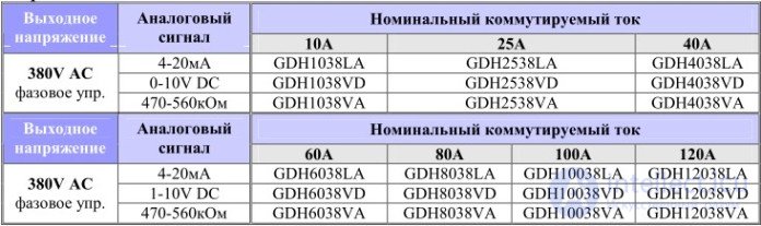
The table below shows the types of control signals for solid state relays with phase control from the company IMPULS.
Note the last letters of the marking (LA, VD, VA); for most manufacturers they are the same and indicate precisely the type of signal.
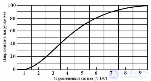
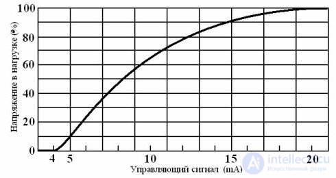
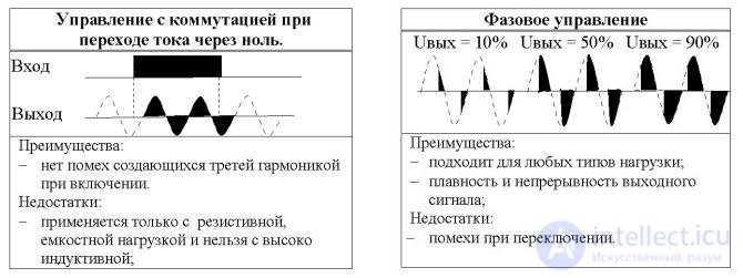
As already mentioned, in phase-controlled relays the output voltage changes depending on the magnitude of the control signal, as shown in the graph below.
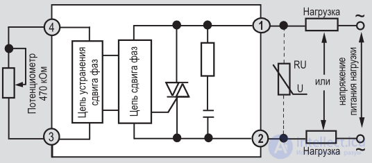
Such a relay can be recognized by the symbol near the input terminals; for example, in the photo below you can see that a 470-560 kΩ variable resistor is connected to the input.
There are also solid state relays with a control signal from a 220V AC mains supply, as shown below. They are suitable for use as replacements for low-power contactors or electromagnetic relays.
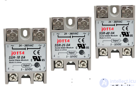
Marking and control type
To determine the "phase count" of a relay, symbols at the start of the marking are used:
SSR — single-phase;
TTR — three-phase.
Which is equivalent to single-pole and three-pole switching devices.
The current rating is also coded; for example, FOTEK indicates it in the form: Pxx (see the FOTEK Automation Equipment Catalog)
Where "xx" is the current rating in amperes, for example, P03 is 3 amperes, and P10 is 10 amperes.
If the marking contains the letter H, then the relay is designed for switching an elevated voltage.
Information about the control type in the marking is given in the last characters; it can vary between manufacturers, but it often has the following form and meaning (data compiled from various manufacturers):
VA — variable resistor 470-560 kΩ / 2 W (phase control);
LA — analog signal 4-20 mA (phase control);
VD — analog signal 0-10V DC (phase control);
ZD — control 10-30V DC (zero-crossing switching);
ZD3 — control 3-32V DC (zero-crossing switching);
ZA2 — control 70-280V AC (zero-crossing switching);
DD3 — control by a 3-32V DC signal, switching a DC circuit (DC voltage switching);
DA — control by a DC signal, switching an AC circuit.
AA — control by an AC signal (220V), switching an AC circuit.
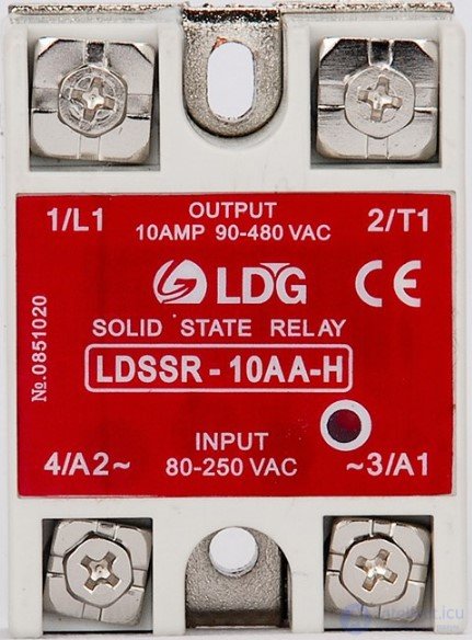
Let's check this in practice. Suppose you come across a device such as the one in the figure below and want to find out what it is.
If you carefully examine the labels near the wire connection terminals, it will already be clear that this is a relay for controlling AC circuits from 90 to 480 volts, with control also performed by an AC signal with a voltage from 80 to 250 volts.
If only the marking is visible, then: "SSR" — single-phase; "-10" — rated current of 10 amperes; "AA" — AC control, AC switching; "H" — for switching elevated voltage in the power circuit — up to 480V (if there were no H, it would be up to 380-400V).
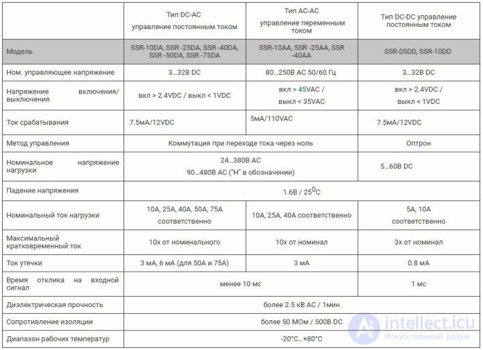
To reinforce and better understand this, study the following table of markings and specifications of solid state relays.
Design
The internal circuit of a solid state relay depends on which current it is designed for (DC or AC) and the type of control signal used. Let's look at some of them.
Let's start with a relay that is controlled by DC and switches at zero crossing. These are sometimes called "Z-type solid state relays."
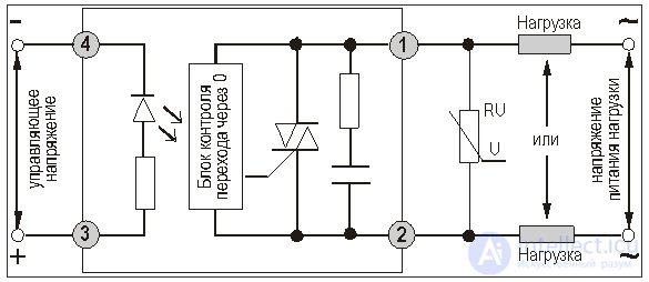
Here, terminals 3-4 are the control signal input, which uses control via an optocoupler that provides galvanic isolation between the input and output circuits.
The zero-crossing detection block, or as it is called, the Zero Cross Circuit, monitors the phase of the supply voltage and switches the circuit (on or off) when it crosses zero. This method is also called Zero Voltage Switching; it reduces current surges on switch-on (since the voltage at that moment is zero) and back-EMF spikes when the load is switched off.
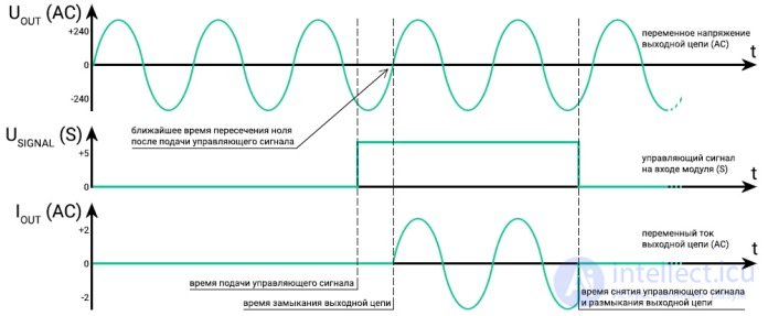
Suitable for controlling resistive, capacitive, and inductive loads. Not suitable for controlling highly inductive loads (at cosφ<0.5), such as unloaded transformers. This control method also does not introduce interference into the supply network during switching. Below you can see the waveforms of the control signal, mains voltage, and load current for this control method.
Schematically this is implemented as follows:
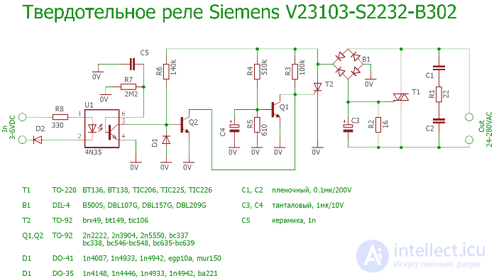
Here, voltage from the mains is supplied to a block containing a triac and a block that monitors the zero crossing. Elements Q1, R3, R4, R5, C4 block the turn-on of thyristor T2, which controls the power triac T1, at high voltage. Switching is then possible only when the mains voltage is close to zero. The input circuit is built on U1, a transistor optocoupler, which sends a signal to the control electrode of the T2 triac driver, via Q2.
Instant-on relays are constructed somewhat differently from zero-crossing relays. They lack the ZCC stage.
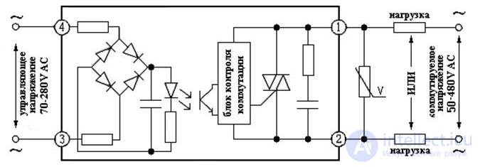
When controlled by AC, the circuit differs only in that it has a rectifier (a diode bridge) at the input.
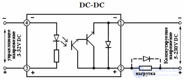
And when switching DC circuits, the triac is replaced with a transistor.
There are also universal relays for both DC and AC that use an assembly of transistors. In general, there are many output-stage circuit designs for solid state relays; below are examples of the circuitry of various models from a manufacturer such as International Rectifier.
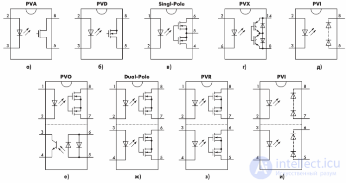
Things are somewhat different in phase-controlled relays. Like a dimmer, it can regulate the load power (output voltage); for this, an analog signal — voltage, current, or a variable resistance — is applied to the input. A thyristor is used here as the power element. But keep in mind that this regulation method causes interference in the network, and mains filters with common-mode chokes are used to suppress it, but that is a completely different topic.
You can see the differences between zero-crossing switching and phase switching in the figure below.
Wiring diagrams and usage features
In fact, the wiring diagram for solid state relays is almost no different from conventional ones. How do you connect it correctly? Let's find out.
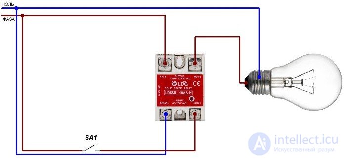
If you need to replace a conventional 220V relay controlled by 220V AC, use the following circuit, using the LDG LDSSR-10AA-H as an example. The diagram shows, as an example, a connection through an ordinary switch or toggle switch. Instead, the turn-on signal could be supplied from a thermostat, a controller, or other devices.
If you need to control a 220V circuit using a low-voltage signal, you can use the FOTEK HPR-80AA (see the FOTEK Solid State Relay Catalog).
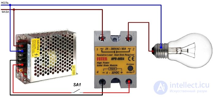
In this circuit, a 12VDC power supply is used as the source of low DC voltage, of the kind widely used as power supplies for LED strips. Incidentally, you can even control such a solid state relay by applying to its input the voltage from a mobile phone charger, since its output is 5V, which is above the minimum signal of 3V.
Also keep in mind that the control voltage needs to be turned off completely, since every relay has certain parameters at which it operates; for example, the one shown above has a turn-off voltage of about 1 volt, and it may trigger not at the rated 3 volts but already at 2.5 volts (the figures given are averaged, for illustration, and may differ depending not only on the specific device but also on the ambient conditions and installation.)
But let us remind you that there are also relays with phase control. Wiring diagrams for such relays are illustrated below (illustration from their instructions).
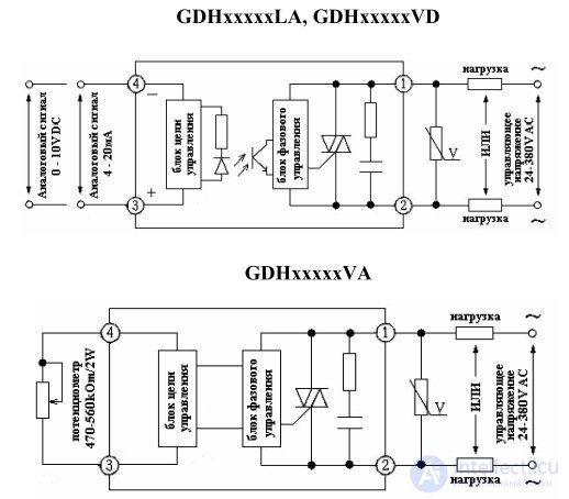
However, using a solid state relay to control a heavy load is impossible without cooling. Passive cooling (a simple heatsink) or active cooling (heatsink + fan) is used for this.
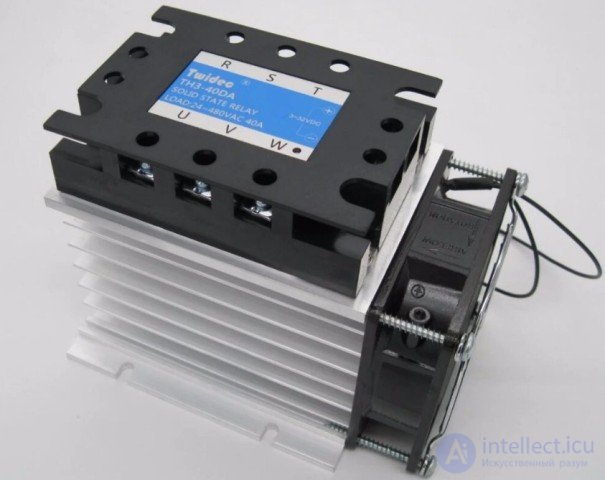
Recommendations on choosing a cooler are given in the technical documentation for the specific solid state relay.
Semiconductor relays heat up during operation. The power dissipated as heat equals the product of the voltage drop across the power switch (about 2 volts) and the current flowing through it;
Under overload and short circuits, there is a high probability of the power switch failing; the overload capacity is typically 10In for 10 ms — one period in a 50 Hz network (may vary depending on the components used);
A circuit breaker most likely will not have time to trip before the relay fails under a short circuit;
Under voltage surges (transients), the service life of a solid state relay can end instantly.
Solid state relays have a leakage current (up to 7-10 mA); because of this, if they are placed in the control circuit of, for example, LED fixtures, the latter will flicker similarly to the situation with an illuminated switch. Accordingly, there will be voltage on the phase wire even when the relay is off!
Conclusion
Solid state relays can be used as a replacement for electromechanical ones in a number of cases. The most popular household application is replacing the contactor in an electric boiler, because of the loud click it makes when switching on; accordingly, the heating elements will also switch on silently.
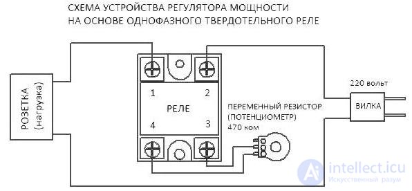
As well as implementing various high-power power regulators for the same heating elements and other loads, for which a solid state relay with an analog input signal from a variable resistance (type VA) is used.
Hobbyists can also build the simplest solid state relay based on a triac optodriver with a ZCC, such as the MOC3041 and similar parts.
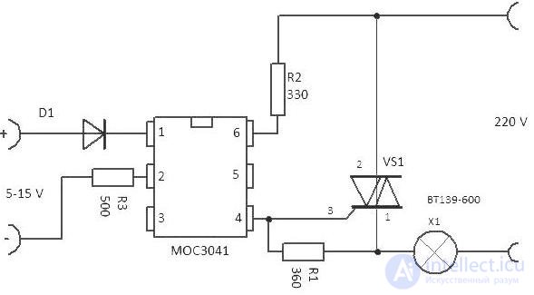
Such relays will last many times longer than contactors, provided there are no overloads, overheating, short circuits, or voltage surges!

Comments