
Lecture
Optotriacs belong to the class of optocouplers and provide very good galvanic isolation (on the order of 7500 V) between the control circuit and the load. These components consist of a gallium arsenide infrared LED coupled through an optical channel with a bidirectional silicon switch. The latter can be supplemented with a triggering circuit that activates at the zero crossing of the supply voltage and is placed on the same silicon chip.
These components are especially indispensable when driving more powerful triacs, for example when implementing high-voltage or higher-power relays. Such optocouplers were designed to provide a connection between low-voltage logic elements (for example, a TTL gate) and a load powered by mains voltage (110 or 220 volts).
Optotriacs are a type of optocoupler with excellent electrical parameters. They create an extremely reliable galvanic isolation, withstanding a voltage on the order of 7.5 kV, between the connected controlled load and the control circuit.
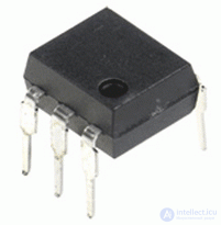
photo of the MOC3063 optotriac
These components are built from a gallium arsenide IR LED coupled to a silicon dual-channel switch. In turn, this switch may include a triggering element that turns on at the moment the supply AC voltage crosses zero.
Optotriacs are exceptionally useful for controlling more powerful triacs. Similar optotriacs were designed to provide a connection between a load powered by a 220-volt AC voltage and low-voltage logic.
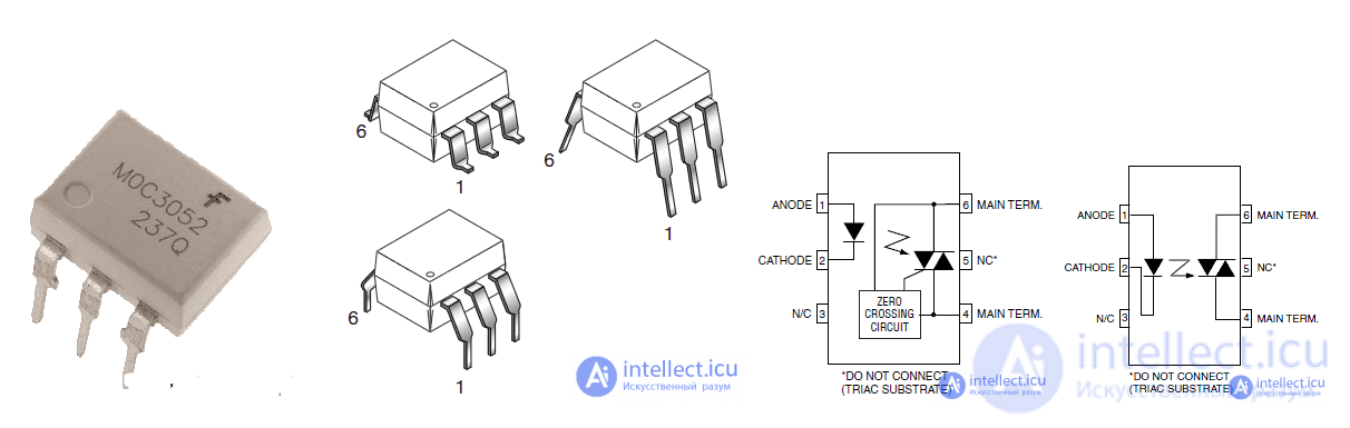
Optotriacs are typically produced in a compact 6-pin DIP package. Its internal circuit, parameters, and pin layout are shown below.
Phototriacs are triacs with photoelectronic control, in which the control electrode is replaced by an infrared LED and a photodetector with a control circuit. The main advantage of such devices is the galvanic isolation of the control circuit from the power circuit. As an example, Fig. 3, a shows the block diagram of a phototriac produced by Siemens under the name SITAC, and its schematic symbol is shown in Fig. 3, b. This device draws about 1.5 mA at the LED control input and switches an output AC current of 0.3 A at voltages up to 600 V. Such devices are widely used as isolated-control AC switches. They can also be used to control more powerful thyristors or triacs, while providing galvanic isolation of the control circuits. The low current draw of the control circuit allows the SITAC to be connected directly to the output of microprocessors and microcontrollers. As an example, Fig. 4 shows the SITAC device connected to a microprocessor for regulating current in a load connected to a 220 V AC mains supply, with a maximum power of up to 66 W.
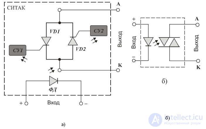
Fig. 3. Structure of the SITAC phototriac (a) and its schematic symbol (b)
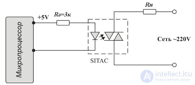
Fig. 4. Connecting the SITAC phototriac to a microprocessor
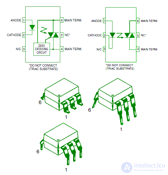
An optotriac can be housed in a compact 6-pin DIP package; its pinout and internal structure are shown in the figures below.
These components are especially indispensable when driving more powerful triacs, for example when implementing high-voltage or higher-power relays.
For solving this problem, any optocoupler with a zero-crossing detector circuit will work. These optocouplers help eliminate the radio interference that is inherent when triacs and thyristors operate.
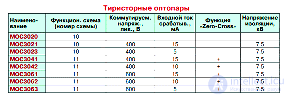
Below is a table; all the selected optocouplers differ in minimum guaranteed control current and maximum operating voltage.
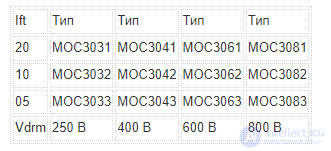
Any of them will work for the task at hand.
There is no point in digging any deeper into the specifications. Let's look at the main parameters and connection diagrams.
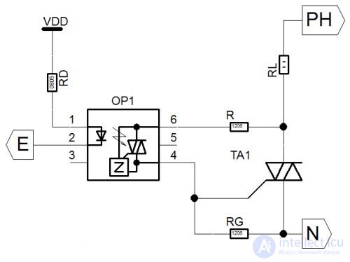
or
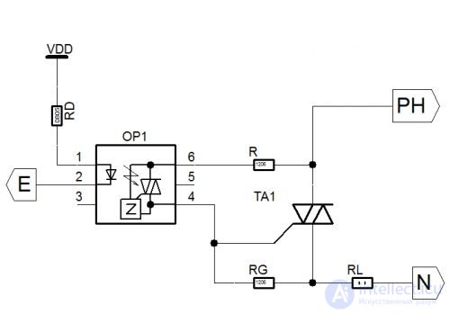
These circuits are not fundamentally different from each other, except for where the load is connected, but I want to point out that the load must be of an active nature. If the load has an inductive component, circuits with protection for the optotriac and the power triac must be used (but we will not cover those here).
In this circuit there are two elements that need to be calculated, but in practice such calculations are rarely done — "calculate it once and use it for a lifetime."
But I believe these techniques are worth knowing.
Calculating the resistance RD.
The value of this resistor depends on the minimum forward current of the infrared LED that guarantees the triac will turn on.
Hence RD=(+VDD -1.5)/If
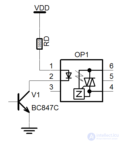
For example, for a transistor-driven control circuit (which is used in temperature controller circuits), with a supply voltage of +12 V and a voltage across the saturated transistor (Uce sat) of 0.3 V, +VDD = 11.7 V, and If must be in the range of 15 to 50 mA for the MOC3041. If = 20 mA should be chosen, taking into account the LED's decreasing efficiency over its service life (a 5 mA margin), to fully ensure the optocoupler operates properly as the current gradually decreases.
Thus we have:
RD=(11.7-1.5)/0.02 = 510 Ohms.
The value obtained even falls within the standard resistor series.
Calculating the resistance R.
If working with a purely active load, this resistor can even be omitted, but that is only suitable for laboratory conditions. So for reliable operation, let me explain how to calculate it and what it is for.
The control electrode of the optotriac can withstand a certain maximum current. Exceeding this current will damage the optocoupler. We need to calculate the resistance so that, at the maximum operating mains voltage (for example, 220 V), the current does not exceed the maximum allowable value.
For the optocouplers mentioned above, the maximum allowable current is 1 A.
Minimum resistance of resistor R:
Rmin=220 V * 1.44 / 1 A = 311 Ohms.
On the other hand, too large a resistance can disrupt the circuit's operation (there will be intermittent triggering of the power triac).
Therefore, a resistance from the standard series of R=330 or 390 Ohms is chosen.
Calculating the resistance Rg.
The resistor Rg is needed only in the case of a highly sensitive triac control electrode. It can typically range from 100 Ohms to 5 kOhms. We recommend using 1 kOhm.
This circuit has two components that need to be calculated, but in practice such parameter calculations are not always performed. Still, let's provide these calculations for reference.
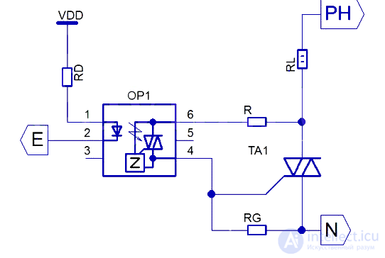
Calculating the RD resistor parameter. The resistance of this resistor depends on the minimum forward current of the IR LED that ensures the triac turns on. Thus,
RD = (+VDD -1.5) / If
Suppose, for a transistor-controlled circuit (which is quite often used in temperature controller circuits) with a supply voltage of 12V and a voltage across the open transistor (Uce) of 0.3 V; VDD = 11.7 V, and consequently the If range is approximately 15 mA for the MOC3041.
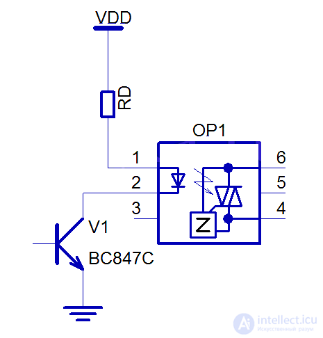
We need to set If = 20 mA to account for the decrease in LED luminous efficiency over its service life (add 5 mA), giving us:
RD=(11.7V — 1.5V)/0.02A = 510 Ohms.
Calculating the R resistance parameter. The control electrode of the optotriac can withstand a certain maximum current. Exceeding this parameter will damage the optocoupler. Therefore, the resistance must be calculated so that, at the highest mains voltage (for example, 220 V), the current does not exceed the maximum allowable value.
As an example, let's take a maximum allowable current of 1A; then the resistance will be:
R=220 V * 1.44 / 1 A = 311 Ohms.
Keep in mind that too large a resistance for this resistor can disrupt the stability of the optotriac's turn-on.
Calculating the Rg resistance parameter. The Rg resistor is connected only if the triac's electrode has increased sensitivity. As a rule, the Rg resistance is in the range of 100 Ohms to 5 kOhms. It is preferable to use 1 kOhm.
If the controlled load has an inductive component, a different connection circuit with protection for the power triac and the optotriac must be used.
The signal coming from the optotriac to the triac's control electrode is only needed to turn it on. However, at a high switching frequency of the commutated voltage, there is a significant probability of the controlled triac turning on spontaneously, even in the absence of a control signal.
Factors causing false triggering can include voltage surges when switching on a key connected to an inductive load, and pulse interference in the load's power lines. An effective way to eliminate these unpleasant issues is to use a snubber (damping) RC network in the circuit, connected in parallel with the output of the key block.
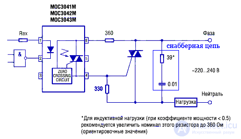
The capacitor in the snubber RC network is a metallized-film type with a rating from 0.01 to 0.1 µF, and the resistor's resistance is 20…500 Ohms. These component values should be regarded strictly as approximate figures.

Comments