
Lecture 23 min.
Fuses are key elements of electrical circuits designed to protect equipment and wiring from overloads and short circuits. Their main function is to interrupt the current when it exceeds a permissible value, thereby preventing damage to components and possible fires.
There are many types of fuses, differing in design, operating principle, and application area. From simple fuse links to complex automatic devices, each type has its own features, advantages, and limitations.
An electrical fuse is a device or switching apparatus designed to disconnect a circuit from the power source when the current significantly exceeds the rated value. In simple terms: if a device for some reason starts drawing excessive current, the fuse will open the circuit. It is installed in series with the protected section of the circuit.
On a circuit diagram, a fuse is denoted as follows:
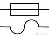
Any electrical system operates on a balance between supplied and consumed energy. When voltage is applied to an electrical circuit, it is applied across a certain circuit resistance. As a result, according to Ohm's law, a current is generated, through the action of which work is performed.
In cases of insulation failure, installation errors, or fault conditions, the resistance of the electrical circuit gradually decreases or drops sharply. This leads to a corresponding increase in current, which, upon reaching a value exceeding the rated value, causes harm to equipment and people.
Safety issues have always been and will remain relevant in the use of electrical energy. That is why protective devices are constantly given increased attention. The first such designs, called fuses, are still widely used today.
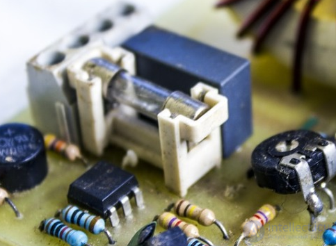
An electrical fuse is part of the working circuit, is inserted into a break in the supply wire, and must reliably withstand the operating load while protecting the circuit from the appearance of excessive currents. This function forms the basis of its classification by rated current.
According to the operating principle applied and the method of breaking the circuit, all fuses are divided into the following groups:
Fuses of this design contain a current-carrying element which, under the action of a current exceeding the rated set value, melts from overheating and vaporizes. This ensures that voltage is removed from the circuit, protecting it.
Fuse links can be made of metals such as copper, lead, iron, zinc, or specific alloys with a coefficient of thermal expansion that provides the protective properties of the electrical equipment.
A fuse link operates based solely on the magnitude of the current flowing through it, not on the voltage — these are its main characteristics.
Rated current (for example, 0.1 A) is the main parameter. If the current exceeds this level (usually slightly above it, for example, 120–150% of the rated value), the fuse will overheat and burn out.
Rated voltage (also indicated on the housing, for example, 250 V or 32 V) is the maximum permissible voltage at which the fuse is able to safely break the circuit. If the circuit voltage is higher than the rated value, an arc may occur when the fuse blows, and the fuse will not interrupt the current.
In summary:
Triggering = depends on current.
Safe disconnection = depends on voltage (and fuse design).
The heating and cooling characteristics of conductors for electrical equipment under steady-state operating conditions are shown in the figure.
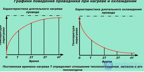
The operation of a fuse link under the design load is ensured by maintaining a reliable temperature balance between the heat generated in the metal by the flow of operating current through it and the heat dissipated into the environment.
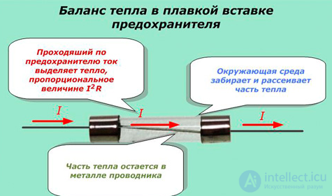
When fault conditions occur, this balance is quickly disrupted.
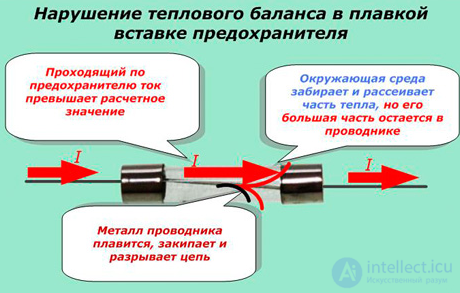
The metal part of the fuse link increases its active resistance when heated. This causes greater heating, since the heat generated is directly proportional to I2R. This in turn increases resistance and heat generation further. The process continues in an avalanche-like manner until melting, boiling, and mechanical destruction of the fuse link occur.
When the circuit breaks inside the fuse link, an electric arc forms. Until it is fully extinguished, a current dangerous to the installation flows through it, changing according to the pattern shown in the figure below.
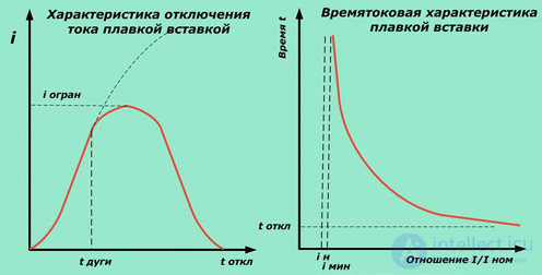
The main operational parameter of a fuse link is its time-current characteristic, which defines the relationship between the ratio of fault current to rated current and the tripping time.
To speed up the operation of a fuse link at low fault-current ratios, special technical techniques are used:
creating variable cross-section shapes with areas of reduced cross-sectional area;
using the metallurgical effect.
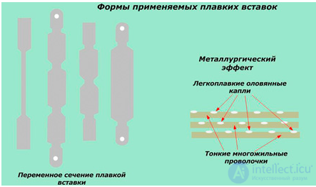
Cross-section variation
At the narrowed sections of the strips, resistance increases and greater heat is generated. Under normal operating conditions, this energy has time to spread evenly across the entire surface, but under overload conditions, critical zones form at the narrow sections. Their temperature quickly reaches a point at which the metal melts and breaks the electrical circuit.
To increase response speed, the strips are made of thin foil and used in several layers connected in parallel. The burning through of any section on one of the layers speeds up the operation of the protection.
It is based on the property of certain low-melting-point metals, such as lead or tin, to dissolve higher-melting-point metals such as copper, silver, and certain alloys within their structure.
To achieve this, drops of tin are applied to the multi-strand wires used to make the fuse link. At the permissible temperature of the wire metal, these additives have no effect, but under fault conditions they quickly melt, dissolve part of the base metal, and speed up the operation of the fuse.
The effectiveness of this method is only apparent on thin conductors and decreases significantly as their cross-sectional area increases.
The main drawback of a fuse link is that after it operates, it must be manually replaced with a new one. This requires keeping a stock of spares on hand.
By shape, fuses can be:
Tube-type (cartridge);
Blade-type (also called flag-type);
Plug-type;
Knife-blade type.
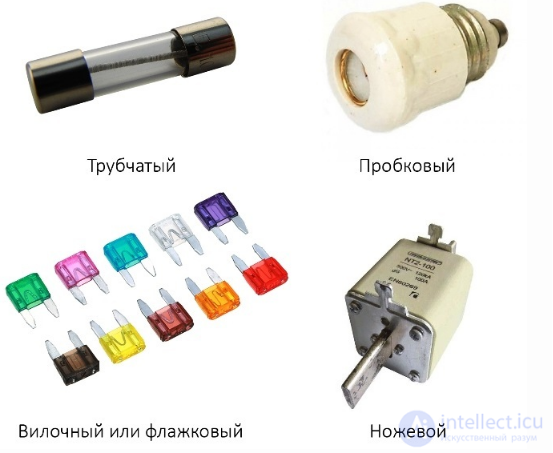
Note:
Blade or flag-type fuses are most often used in automotive wiring. Plug-type fuses were used (and are still found today) for protecting apartment wiring and other circuits, for example, installed at the electricity meter. Knife-blade fuses are used in power electrical cabinets (for example, in switchgear cabinets such as YAVR, YARP, ShR).
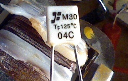
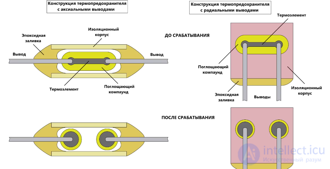
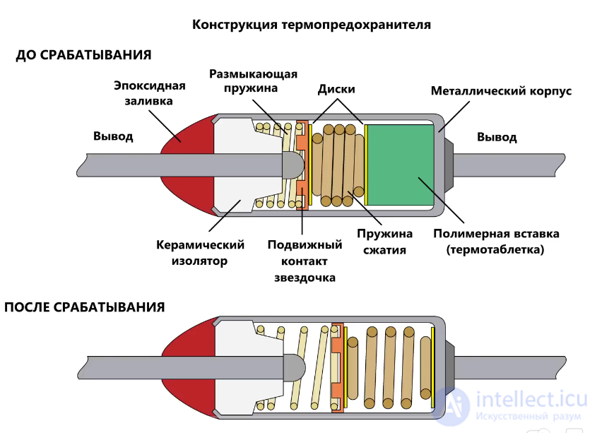
are designed to operate at a specific current within a permissible temperature range. They are also single-use, like fuse links.
Thermal fuses are single-use protective elements, just like fuse links. They are used in circuits where protection is needed not only against excess current but also against overheating.
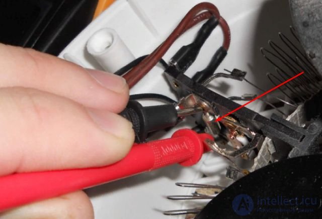
For example, they are used in modern household heaters. In the photo you can see a thermal fuse in a fan heater. It burns out if the permissible temperature is exceeded, for example, if the fan fails, so that the heating coils do not overheat and cause a fire. They are also used in hair dryers, irons, and other appliances.
The main characteristics to consider when choosing a fuse are its rated current and temperature — take both of these factors into account when purchasing a replacement for a failed element.
It is also worth noting that single-use thermal fuses are often installed to protect the windings of modern transformers. If it is located on top of the winding, you will be able to replace it and the transformer will continue to serve; but if it is located deep inside the winding, you will not be able to replace it without rewinding skills.
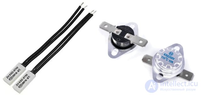
But there are also reusable thermal fuses. In these, a contact group opens or switches under the influence of heat. They come with normally closed (NC) and normally open (NO) contacts. The former open the circuit when heated, while the latter, on the contrary, close it. After cooling, the contacts return to their original position.
Therefore, when buying a new one to replace a failed unit, pay attention to the contact type (NC or NO).
An electromechanical fuse is sometimes the term used for a circuit breaker. It is used to protect wiring, electric motors, and other relatively powerful electrical devices.
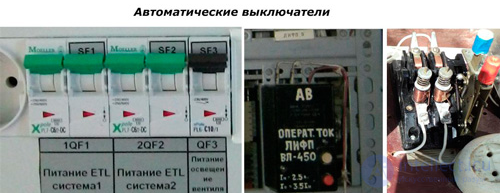
During their operation, a special sensor continuously monitors the magnitude of the current flowing. Once a critical value is reached, a control signal is sent to the actuating mechanism — a spring cocked by a thermal or magnetic trip unit.
An electronic fuse is built on a measuring circuit, a control circuit, and a power transistor that opens the circuit once the threshold current is reached. The most common device operating on this principle is the protection board of a lithium battery.
In these designs, the function of protecting the electrical circuit is performed by contactless electronic switches based on power semiconductor devices such as diodes, transistors, or thyristors.
They are called electronic fuses (EF) or current monitoring and switching modules (CMSM).
As an example, the figure shows a block diagram illustrating the operating principle of a transistor-based fuse.
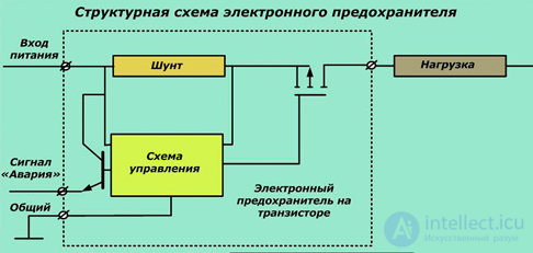
The control circuit of such a fuse picks up the measured current signal from a shunt resistor. It is processed and applied to the input of the isolated semiconductor gate of a MOSFET-type field-effect transistor.
When the current through the fuse begins to exceed the permissible value, the gate closes and the load is disconnected. The fuse then switches into a self-latching mode.
If a piece of electrical equipment uses many CMSMs, difficulties arise in identifying which fuse has tripped. To make finding it easier, a "Fault" signal function has been introduced, which can be indicated by an LED lighting up or by the activation of a solid-state or electromechanical relay.
Such electronic fuses are notable for their speed, with a tripping time not exceeding 30 milliseconds.
The circuit discussed above is considered simple; it can be significantly expanded with additional functions, such as:
continuous monitoring of current in the load circuit, generating trip commands when the current exceeds the rated value by more than 30%;
disconnecting the protected section in the event of short circuits or overloads, issuing a signal when the load current rises more than 10% above the set threshold;
protecting the power transistor element when temperatures exceed 100 degrees.
In such circuits, the CMSM modules used are divided into 4 groups by tripping time. The fastest-acting devices are classified as class "0". They disconnect currents exceeding the set threshold by 50% within 5 ms, by 300% within 1.5 ms, and by 400% within 10 μs.
These protective devices differ from fuse links in that after the fault load is removed, they retain their functionality for further repeated use. That is why they are called self-resetting fuses.
Their design is based on polymer materials with a positive temperature coefficient of electrical resistance. They have a crystalline lattice structure under normal conditions and rapidly transition to an amorphous state when heated.
The tripping characteristic of such a fuse is usually presented as the logarithm of resistance as a function of the material's temperature.
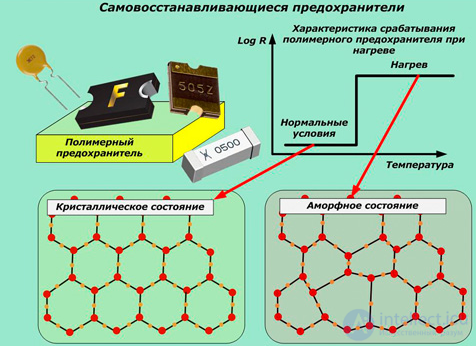
When the polymer has a crystalline lattice, it conducts electric current well, like a metal. In the amorphous state, conductivity deteriorates significantly, which causes the load to be disconnected when an abnormal condition occurs.
Such fuses are used in protective devices to handle repeated overloads occurring in situations where replacing a fuse link or manual operator intervention is difficult. This is the domain of automatic electronic devices widely used in computer technology, mobile gadgets, measurement and medical equipment, and vehicles.
The reliable operation of self-resetting fuses is affected by ambient temperature and the magnitude of the current flowing through them. To account for this, the following technical terms have been introduced:
hold current, defined as the maximum value at a temperature of +23 degrees Celsius that does not cause the device to trip;
trip current, the minimum value that, at the same temperature, causes the polymer to transition into the amorphous state;
the maximum value of applied operating voltage;
tripping time, measured from the onset of the fault current to disconnection of the load;
dissipated power, defining the fuse's ability to transfer heat into the environment at +23 degrees;
initial resistance before being put into operation;
resistance reached 1 hour after tripping.
Self-resetting fuses feature:
small dimensions;
fast tripping;
stable operation;
combined protection of devices against overcurrents and overheating;
no need for maintenance.
Self-resetting fuses are devices with a positive temperature coefficient of resistance. As the current increases, their resistance increases nonlinearly. The resistance after tripping depends on two factors, namely, the applied voltage and the dissipated power.
R=U2/P
Below you can see an example of a resistance-versus-temperature graph.
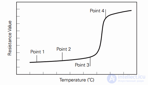
As resistance rises, so does the device's temperature, up to about 80 degrees. They consist of a mixture of polymers and carbon.
They have the following technical characteristics:
Vmax — the maximum permissible voltage.
Imax — the maximum current that can flow through the circuit without destroying the self-resetting fuse.
Ihold — the rated current.
Itrip — the minimum current that can flow through the device without causing it to trip.
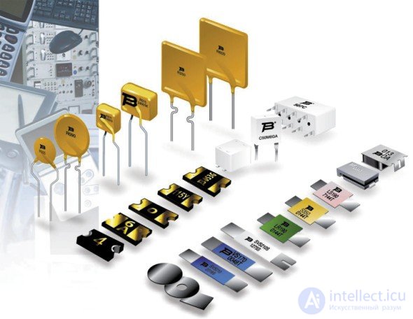
Self-resetting fuses are often used to protect digital electronics, for example, to protect USB and HDMI ports, and less often in the power circuits of portable battery-powered devices.
Depending on the intended application, fuses are designed to work in the circuits of:
industrial installations;
general-purpose household appliances.
Since they operate in circuits of different voltages, their housings are made with distinct dielectric properties. Based on this principle, fuses are divided into designs intended for use:
with low-voltage devices;
in circuits up to 1000 volts inclusive;
in high-voltage industrial equipment circuits.
Special-purpose designs include fuses that are:
explosion-type;
puncture-type (breakdown fuses);
designed for arc quenching upon circuit interruption through narrow channels filled with fine-grained filler material, or through gas-blast or liquid-blast action;
for vehicles.
The fault current limited by fuses can range from a fraction of an ampere to a kiloampere.
Sometimes electricians install a calibrated wire in the housing instead of a fuse link. This approach is not recommended, because even with a precisely selected cross-section, the electrical resistance of the wire may differ from the recommended value due to the properties of the metal or alloy itself. Such a fuse will not operate accurately.
An even bigger mistake is the use of homemade "bridges" installed at random. These are most often the cause of accidents and fires occurring in electrical wiring.
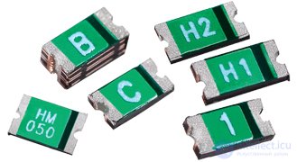
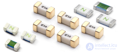
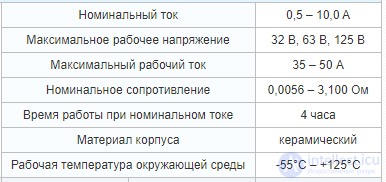
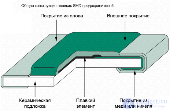
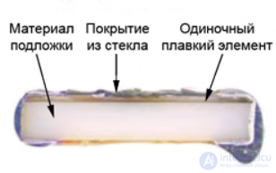
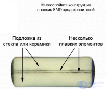
SMD (chip) fuses get their name from the method of mounting them on the surface of a printed circuit board, where SMD (Surface-Mount Device) refers to a surface-mount component. They are used in DC circuits to protect against current overload, with voltages up to 125 V and currents up to 100 A.
SMD fuses are divided into fuse-link (fusible) and self-resetting types.
The polymer crystalline structure of a self-resetting fuse allows it to restore its original conductive characteristics once the triggering influence has ended. A fusible SMD fuse must be replaced after it trips.
The main parameters of surface-mount fuses (rated current, rated resistance, dissipated power, and tripping time) depend on changes in ambient operating temperature. Fast-acting fusible SMD fuses are used in computer technology, telephony, digital video cameras, LCD displays, and other electrical equipment.
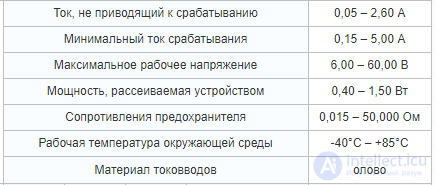
Self-resetting SMD fuses are used in computer and automotive electronics, telecommunications, alarm and measurement equipment, satellite television, and other electronic equipment. Detailed characteristics and main parameters of SMD fuses are given in the tables. The marking decoding, dimensions, and mounting and soldering recommendations are provided below. The warranty period for the SMD fuses supplied by our company is 2 years. This is backed by appropriate quality documentation. The final price for a specific SMD fuse depends on quantity, delivery time, manufacturer, country of origin, and payment method.
Key parameters
IH – Maximum hold current — the maximum current that a self-resetting fuse can conduct without tripping.
IT – Minimum trip current — the minimum current through a self-resetting fuse that causes it to switch from the conducting state to the non-conducting state.
UMAX – Maximum operating voltage — the maximum voltage that a self-resetting fuse can withstand without being destroyed while conducting its rated current.
IMAX – Maximum permissible current — the maximum short-circuit current that a self-resetting fuse can withstand without being destroyed at its rated voltage.
PD MAX – Maximum power dissipated by the fuse — the maximum power dissipated by the fuse after transitioning from the conducting state to the non-conducting state.
RMIN – Minimum resistance — the minimum resistance of a self-resetting fuse in its operating, conducting state.
R1 MAX – Maximum resistance — the maximum resistance of a self-resetting fuse 1 hour after its last trip.
Trip speed – the time to transition from the conducting state to the non-conducting state at a specified current. IH, IT, PD MAX, and trip speed depend on ambient temperature and are given for t = 23°C.
Marking of self-resetting SMD fuses:

SMD – Self-resetting fuse series: "Surface-Mount Device" - for surface mounting.
2920 – Package form factor (dimensions): 0805 - 2.0×1.2 mm; 1206 - 3.2×1.6 mm, 1812 - 4.5×3.2 mm, 2920 - 7.5×5.5 mm.
185 – Rated current, given in hA.
| SMD | - | 1206 | FT | - | 500 |
| SMD | – | Fusible fuse series: "Surface-Mount Device" - for surface mounting. |
| 1206 | – | Package form factor (dimensions): 0603 - 1.6×0.8 mm; 1206 - 3.2×1.6 mm. |
| FT | – | Trip speed: "Fast Trip" - fast-acting. |
| 500 | – | Rated current, given in hA. |
| 2N | - | 100 | L |
| 2N | – | Fusible fuse series. |
| 100 | – | Rated current: for 2N-0100L - 2N-0800L given in hA, for 2N-010L - 2N-100L given in daA. |
| L | – | Fuse variant: gold-plated leads. |

Comments