
Lecture
A semiconductor diode is an electrical energy conversion device that generally contains one or more electrical junctions and two terminals for connection to an external circuit. The operating principle of most diodes is based on various physical phenomena occurring at electrical junctions. The most commonly used junctions in diodes are electron-hole junctions, metal-semiconductor contacts, and anisotype heterojunctions. However, there are diodes whose structure does not contain a rectifying electrical junction at all (for example, the Gunn diode), or that contain several junctions (for example, the p-i-n diode, the thyristor diode/dinistor), as well as diodes with a more complex junction structure (for example, MDM- and MDS-diodes, etc.).
A semiconductor diode is a semiconductor device — in the broad sense, an electronic device made from semiconductor material with two electrical leads (electrodes). In the narrower sense, it is a semiconductor device whose internal structure contains a single p-n junction.
Unlike other types of diodes, such as vacuum diodes, the operating principle of semiconductor diodes is based on various physical phenomena of charge transport in a solid-state semiconductor and their interaction with the electromagnetic field within the semiconductor.
Semiconductor diodes are semiconductor devices with a single p-n junction and two leads.
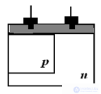 A semiconductor device with a single electrical junction, whose function is to convert one set of electrical values into another, is called a diode. The design of this device provides for two leads for mounting.
There are also diode assemblies with multiple leads.
[[s|diodecurve]]
An ideal diode has zero current when reverse-biased (positive on the cathode, negative on the anode), and zero voltage drop across it when forward-biased (positive on the anode, negative on the cathode). It has no internal inductance or capacitance. Switching occurs instantaneously, meaning that as soon as the current polarity reverses, the conductivity changes immediately — current appears and the voltage drop disappears, or the current disappears and a voltage drop appears.
An ideal semiconductor diode dissipates no power, since dissipated power equals the product of current and voltage, and in an ideal diode either the current or the voltage is always zero.
An ideal diode never heats up, has zero dimensions, and takes up no space on the board. It produces no noise and introduces no noise interference into the current passing through it. An ideal diode can withstand any voltage and any current.
If it were possible to create an ideal diode, only one type of diode would ever be needed — the "simply ideal semiconductor diode." It could be used in every circuit. But no such device has been created yet. Whether it can be created at all is a big question.
Real diodes have some reverse current, a saturation voltage (the voltage drop across the diode at a given forward current through it), a turn-on time (the time after which current appears once forward voltage is applied), and a turn-off time (the time after which current stops if the diode was previously conducting in the forward direction and is now switched to reverse), and a breakdown voltage (the reverse voltage at which the diode becomes conductive, i.e. breakdown occurs). Real diodes have limits on average and pulse current and on dissipated power. Real diodes also have capacitance and inductance.
The same type of diode can be manufactured in various packages. For portable devices, the best option is diodes in an SMD form factor. In these, wire leads are replaced with contact pads. This gives them minimal overall dimensions and also makes it possible to move away from through-hole mounting on printed circuit boards toward surface mounting. Today more than 95% of portable devices are assembled using surface mounting. It is easy to automate, and soldering is done using an infrared oven or a manual hot-air soldering tool.
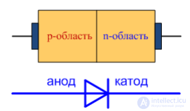
Figure 3.1 — Simplified structure and schematic symbol of a semiconductor diode.
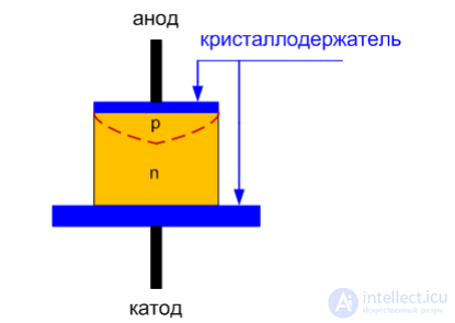
Figure 3.1 — Construction of a planar diode.
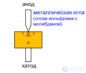
Figure 3.1 — Construction of a point-contact diode.
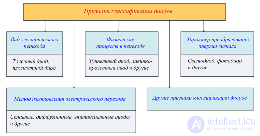
The term "semiconductor diode" covers a wide range of devices with different purposes. Devices with a single p-n junction:
Devices with other kinds of semiconductor structures:
Photoelectric devices with a p-i-n type structure:
Also, among other things, diodes include:
Planar diodes have relatively high capacitance characteristics. As frequency increases, the capacitive reactance decreases, which leads to an increase in the diode's reverse current. At high frequencies, because of this capacitance, the reverse current can reach the magnitude of the forward current, meaning the diode thereby loses its main property of one-way conductivity. To preserve its functional properties, it is necessary to reduce the diode's capacitance. This is achieved using various technological and design methods aimed at reducing the area of the p-n junction.
In diodes used in circuits operating with high-frequency current, devices with point-contact and micro-alloy p-n junctions are used. The required point-contact p-n junction is formed at the point of contact between the sharpened tip of a special metal needle and the semiconductor. This uses a method called electroforming, in which pulses of electric current pass through the connection between the wire and the semiconductor crystal, forming a p-n junction at their point of contact. Diodes are called micro-alloy diodes when their p-n junction is created by electroforming a contact between a semiconductor wafer and a metal object with a flat end face.
The SMD form factor is not suitable for high-current diodes. That is why such diodes are manufactured in a classic two-lead package. At diode currents above 10 amperes, forced cooling of the diode must already be provided. For this purpose they are fitted with a bolt and nut for mounting to a heat-dissipating radiator. Today, rectifier diodes are produced in series with a maximum permissible current of up to 2500 A and a voltage of 2000 volts. Such models are made in a disc-shaped package about 70 mm in diameter. Both end faces serve as current-carrying leads and heat-dissipating surfaces. Rectifier diodes are often made as assemblies of four (a diode bridge).
General-purpose pulse diodes are used in large numbers in the manufacture of household electronic devices. There, they are used to implement logical operations and to rectify small currents. Their production volumes are the largest of all. Their wholesale price is a few cents or less.
Zener diodes are simple sensors that respond to changes in voltage. This is exactly the function they perform in voltage stabilizers. By arranging a special circuit, a low-power Zener diode can be used to stabilize significant currents.
Varicaps are an essential component of modern radio-frequency circuits. They are used to implement modulation and frequency tuning. The most important characteristic of a varicap is its capacitance range and its quality factor (Q). This determines the operating frequency at which the varicap can be used. Microwave circuits require very high Q values.
the system of parameters is given in reference manuals.
This system makes it possible to correctly select a diode for use under specific conditions.
I_f — forward current, flowing in the forward direction,
U_f — forward voltage,
I_f max — maximum available forward current,
U_r max — maximum available reverse voltage,
I_r — diode reverse current,
U_r — diode reverse voltage (the constant voltage applied to the diode in the reverse direction).
Example: KD204A, I_f = 2 A, U_r max = 400 V,
U_f = 1.4 V, I_r = 150 µA
Diodes, as nonlinear elements, are characterized by
static resistance Rc = U/I
differential (dynamic) resistance R_diff = ∆U/∆I
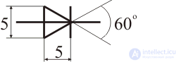
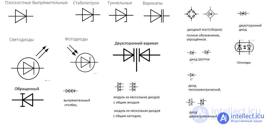
General diode symbol
This is how rectifier, high-frequency, and pulse diodes are denoted on circuit diagrams.
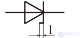
Symbol for Zener diodes
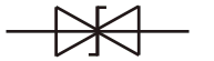
Symbol for a bidirectional Zener diode
A bidirectional Zener diode is more often called a dual-anode Zener diode. Its main advantage is that it can be connected regardless of polarity. Moreover, Zener diodes of the same type designation can be either bidirectional or unidirectional — for example, KS162, KS168, KS133, and others come in metal (or glass) packages and are unidirectional, while those in plastic, usually red, packages are dual-anode.
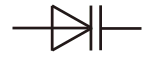
Symbol for a varicap
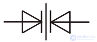
Symbol for a varicap array
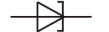
Symbol for a tunnel diode
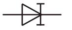
Symbol for a backward tunnel diode
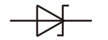
Symbol for a Schottky-barrier diode (Schottky diode)
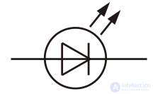
Symbol for an LED
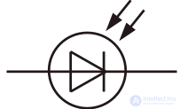
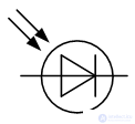
Symbol for a photodiode
Planar
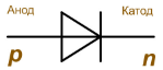
Depending on the diode's design, its symbol may include additional marks. This is according to the website https://intellect.icu. In any case, the apex of the triangle adjoining the diode's axis line indicates the direction of current flow. On the side of the symbol where the triangle is located lies the p-region, also called the anode or emitter, while on the side where the line segment adjoins the triangle lies the n-region, correspondingly called the cathode, or base.
Rectifier Zener diode 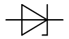 Tunnel Varicaps LEDs Photodiodes
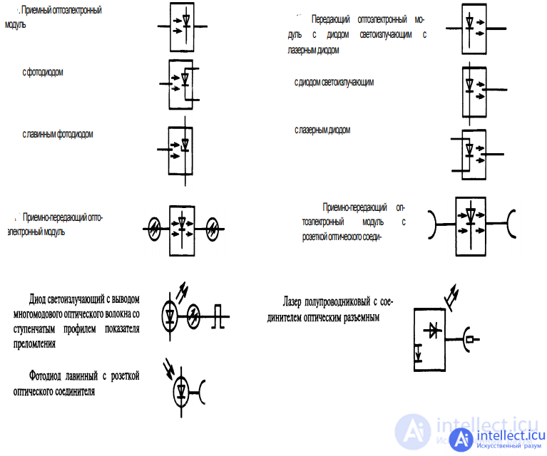
Schematic symbols of elements, components, and devices of fiber-optic transmission systems using diodes
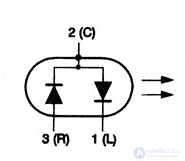
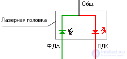
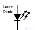
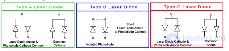
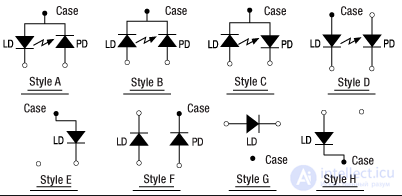
symbol for laser diodes
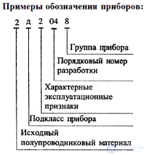
1 — starting material:
germanium — letter G or digit 1;
silicon — letter K or digit 2;
gallium — letter A or digit 3;
indium — letter I or digit 4
2 — device type:
A — microwave diodes
B — varicaps
D — rectifier and pulse diodes
I — tunnel diodes
L — emitting diodes (LEDs)
N — diode thyristors (dinistors)
S — Zener diodes
Ts — rectifier stacks and blocks
3 — digits denote certain basic parameters of the diode (power) (for Zener diodes, the fourth element characterizes the stabilization voltage),
4 — letters and/or digits denoting the design's sequential number
5 — a letter defining the classification by parameters.
Semiconductor diodes whose purpose is to convert alternating current into direct current are called rectifier diodes. Rectification of alternating current using a semiconductor diode is based on its one-way conductivity, which consists in the diode offering very low resistance to current flowing in the forward direction and sufficiently high resistance to current flowing in the reverse direction.
In order to rectify high currents without risking thermal breakdown, diode construction must provide for a substantial p-n junction area. For this reason, rectifier semiconductor diodes employ special p-n junctions built using the latest advances in science and technology.
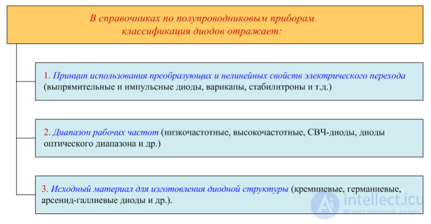
The technology for creating a p-n junction is achieved by introducing an impurity into a p-type or n-type semiconductor, which creates a region of opposite conductivity type within it. Impurities can be added by the alloying method or by the diffusion method.
Diodes produced by the alloying method are called "alloyed" diodes, while those produced by the diffusion method are called "diffusion" diodes.
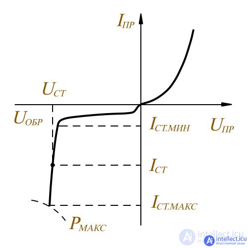
Zener diode characteristic curve
Current-voltage characteristic (I-V curve) of a real diode
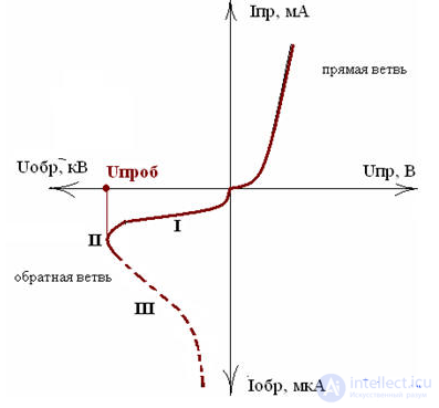
For technical purposes, the I-V curve is used in linear coordinates.
At large reverse-bias voltages, breakdown can develop in the diode — a sharp increase in reverse current with only a slight change in voltage. In avalanche breakdown, electrons in the electric field of the p-n junction gain enough energy to ionize the semiconductor's own atoms. This leads to avalanche multiplication of charge carriers, a sharp increase in their local concentration, and a corresponding increase in current. After avalanche breakdown develops, the diode does not lose its functionality. This type of breakdown is used in semiconductor Zener diodes, whose properties will be discussed further below.
Thermal breakdown develops as a result of local heating of the p-n junction region and, as a consequence, an increase in carrier concentration. Thermal breakdown is irreversible; after it occurs, the diode loses its properties and its functionality.
Current-voltage characteristic of an ideal diode
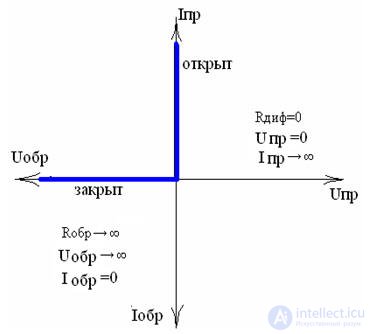
Zener diodes are used to stabilize voltage levels from roughly 3.5 V upward. To stabilize a constant voltage below 1 volt, voltage-reference diodes (stabistors) are used. In stabistors, it is not the reverse branch but the forward branch of the current-voltage characteristic that is used. This is why they are connected not in reverse, as is done with Zener diodes, but in the forward direction. Electronic components such as stabistors and Zener diodes are generally made from silicon.
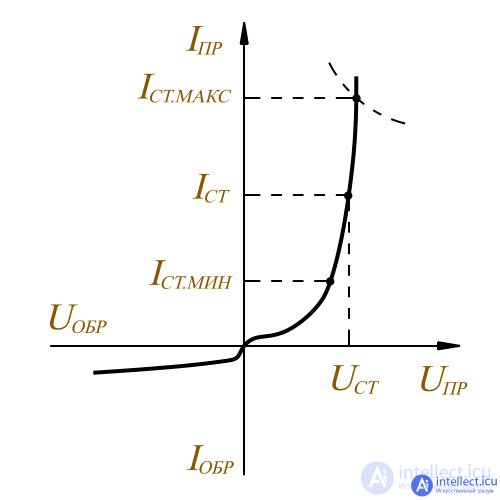
Current-voltage characteristic of a stabistor
The current-voltage characteristic of a diode is described by the Shockley equation:
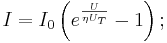
where
 — current through the diode,
 — voltage between the terminals,
 — dark saturation current,
 — ideality factor,
 — thermal voltage (about 25 mV at 300 K),
 — absolute temperature of the p-n junction,
 C — elementary charge,
 J/K — Boltzmann's constant.
The dark saturation current is the diode's leakage current, determined by its design, and serves as a scaling factor. The ideality factor is likewise a design characteristic of the diode. For an ideal diode it equals 1; for real diodes it ranges from 1 to 2 depending on various parameters (junction abruptness, doping level, etc.)
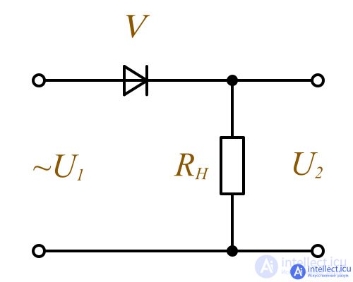
The simplest rectifier
During the positive half-cycle of the input voltage U1, diode V operates in the forward direction, its resistance is small, and the voltage U2 across the load RH is practically equal to the input voltage.
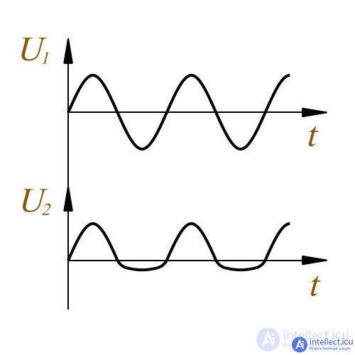
Graph of the input and output voltage of the simplest half-wave rectifier
During the negative half-cycle of this input voltage, the diode is connected in the reverse direction, where its resistance becomes much greater than the load resistance, and almost all of the input voltage is dropped across the diode, while the voltage across the load approaches zero. In such a circuit, only one half-cycle of the input voltage is used to obtain the rectified voltage, which is why this type of rectifier is called a half-wave rectifier.
Semiconductor diodes used to stabilize a constant voltage across a load are called Zener diodes. Zener diodes make use of the reverse section of the current-voltage characteristic in the electrical breakdown region.
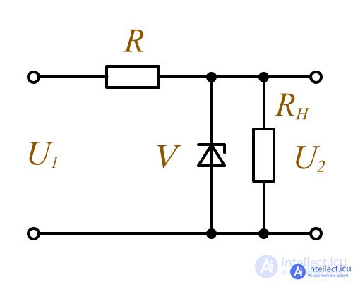
Circuit of the simplest voltage stabilizer
In this case, as the current through the Zener diode changes from I_st.min to I_st.max, the voltage across it remains practically unchanged. If the load RH is connected in parallel with the Zener diode, the voltage level across it will likewise remain unchanged over the specified range of current variation through the Zener diode.
| LEDs |
|
|
|---|---|---|
| Rectifiers |
|
|
| Generator diodes |
|
|
| Voltage-reference sources |
|
|
| Other |
|

Comments