
Lecture
So far we have talked only about amplifiers built from ordinary discrete components. But in radio engineering, integrated amplifiers are becoming increasingly important, being used at both low and high frequencies. In general, the problem of designing integrated circuits, although extremely important, is only touched upon briefly in this book. However, the reader should understand that many of the solutions presented here using bipolar transistors are primarily applied inside integrated circuits, implemented either as multifunctional devices or as devices oriented solely toward performing the single function of signal amplification (operational amplifiers).
The circuit design of integrated amplifiers has a number of features that we have practically not touched on in the earlier description of low-frequency and high-frequency amplifiers. All these features are dictated primarily by the limitations inherent in the manufacturing technology of the integrated circuits themselves.
First, it is extremely difficult to implement capacitors and inductors inside a chip. This means that the only way to couple stages in multistage amplifiers turns out to be direct coupling, i.e., integrated amplifiers are inevitably DC amplifiers. To shape the frequency response of such an amplifier, correction networks made of discrete components external to the chip are used. This limitation leads to significant problems in matching stages and forces the inclusion of many additional networks in the circuit that could be avoided when using discrete components (as a rule, chip designers are not too limited by the number of transistors used in the amplifier, so the presence of a large number of additional networks of various functional purposes creates a problem only for those who are trying to understand how a particular chip works).
The second feature of integrated technology is the difficulty of implementing transistor structures of different types (bipolar and field-effect) on a single silicon die. Thus, integrated amplifiers can be built either solely on the basis of bipolar transistors or solely on the basis of field-effect transistors (of course, technology is improving, and this limitation can sometimes be circumvented).
The third aspect relates to the operating modes of the transistors in integrated amplifiers. The desire to minimize supply currents leads to the emergence of quite special transistor structures operating at very low currents and voltages. Such transistors are not found in discrete form and require special study.
When designing amplifiers from discrete components, one has to calculate the thermal regime for each transistor individually. In integrated circuits this is not the case. Since all the devices are located on a single die, heating of one of them automatically means heating of all the others to the same temperature (of course, this does not happen instantaneously), i.e., as a rule, there is no need to track the thermal regime "device by device." But, on the other hand, the problem of thermal stability becomes one of the most important, since the operating temperature of all the amplifier stages can vary over a very wide range.
In an integrated circuit it is impossible to create coupling capacitors with a capacitance greater than a few tens of picofarads; therefore, circuits are generally designed as DC amplifiers. The standard input stage of an integrated circuit is a differential amplifier, since it guarantees low drift and provides both an inverting and a non-inverting input. In most integrated circuits, some form of emitter follower is used as the output stage, which results in a low output impedance.
Figure 8.11 shows the internal structure of an integrated amplifier. The circuit begins with the obligatory differential stage (on transistors T1 and T2), then includes a voltage amplifier (on transistor T3), and has as its output stage an emitter follower on complementary transistors (T4 and T5) operating in class AB. Diodes D1 and D2 provide bias for the output transistors sufficient to minimize "crossover" distortion (see section 5.17).
When looking at the circuits of integrated amplifiers provided by manufacturers, it can sometimes be difficult to see even an approximate resemblance to the circuit shown in Fig. 8.11. This happens not because of fundamental differences, but because transistors are the cheapest components of all — from the point of view of manufacturing inside an integrated circuit; whenever a transistor can be used instead of a resistor in some part of the circuit, that is what is done. In addition, sometimes when various transistors are created by diffusion on the same silicon substrate, adjacent doped layers form undesirable "parasitic" transistors, and it
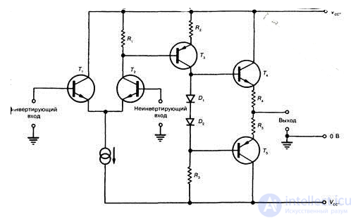
Fig. 8.11. Schematic representation of a typical integrated amplifier.
becomes necessary either to deliberately incorporate these transistors into the circuit or to minimize their effect. As a result of such design constraints, it is sometimes difficult to interpret the circuit in the terms normally used to describe its discrete-component equivalent. However, the reader can be confident that most integrated amplifiers behave as though they looked like the circuit shown in Fig. 8.11.
Integrated linear chips include the amplifier stages discussed in Chapter 4, as well as their combinations and improved variants. They differ from amplifiers built from discrete elements only in the methods used to manufacture the individual circuit components and the technology used to manufacture the finished functional blocks. In most cases, the schematic diagrams of integrated amplifiers look considerably more complex than their discrete counterparts. This is because if a slight improvement in some amplifier parameter requires the introduction of one or more additional transistors, they are generally added, since doing so does not significantly change the manufacturing cost.
Thus, an integrated amplifier is a complete functional block manufactured in a single package, having the parameters specified in its technical specifications, whose schematic diagram cannot be modified in any way not foreseen during its design.
When the required supply voltages are connected and the necessary connections are made, such a complete functional block has the parameters specified in the industry standards for the use of that amplifier.
When using integrated circuits, there is no longer a need to calculate, assemble, and adjust individual stages. In this case, the issues that come to the fore are matching the individual chips, introducing feedback networks that provide the required parameters, ensuring the stability of the entire system covered by feedback loops, and so on.
At present, industry has developed and produces a considerable number of different chips in which amplifiers are just one of the functional blocks among blocks with other purposes. In order to distinguish which function a particular chip performs, a system of designations has been adopted that reflects their membership in certain series, classes, and groups.
A series combines a number of individual functional circuits according to their manufacturing technology, compatibility of supply voltages, signal levels, input and output impedances, package design, and mounting methods. Series are generally designed so that a complete device can be built from the chips belonging to it.
The designation of a chip consists of the following elements.
The first element is a digit indicating the group of the chip. By design and technology, chips are divided into three groups, which are assigned the designations: 1; 5; 6; 7 — semiconductor (7 — chip-scale, without a package); 2; 4; 8 — hybrid; 3 — other (film, vacuum, ceramic, etc.); the second element is two or three digits indicating the sequential development number of the chip series. These elements determine the chip series; the third element is two letters indicating the subgroup and type of chip in accordance with Table 5.1; the fourth element is the sequential development number of the IC within that series.
Table 5.1
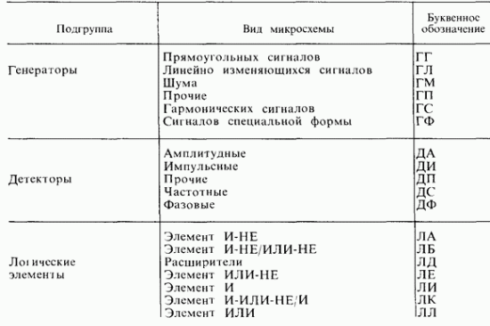
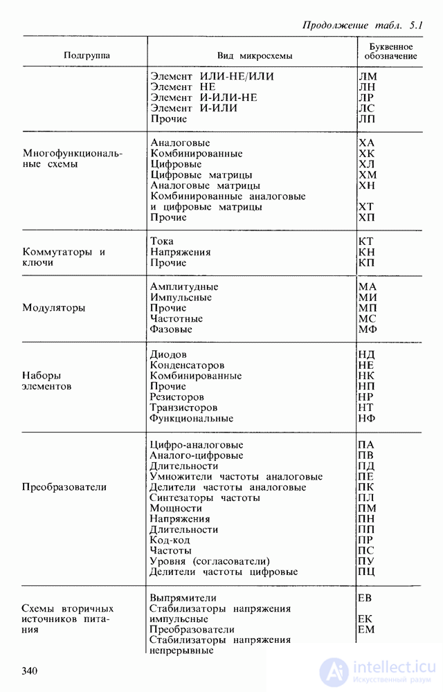
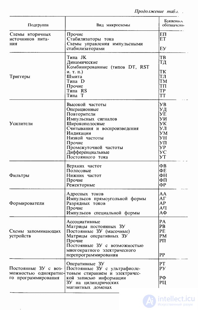
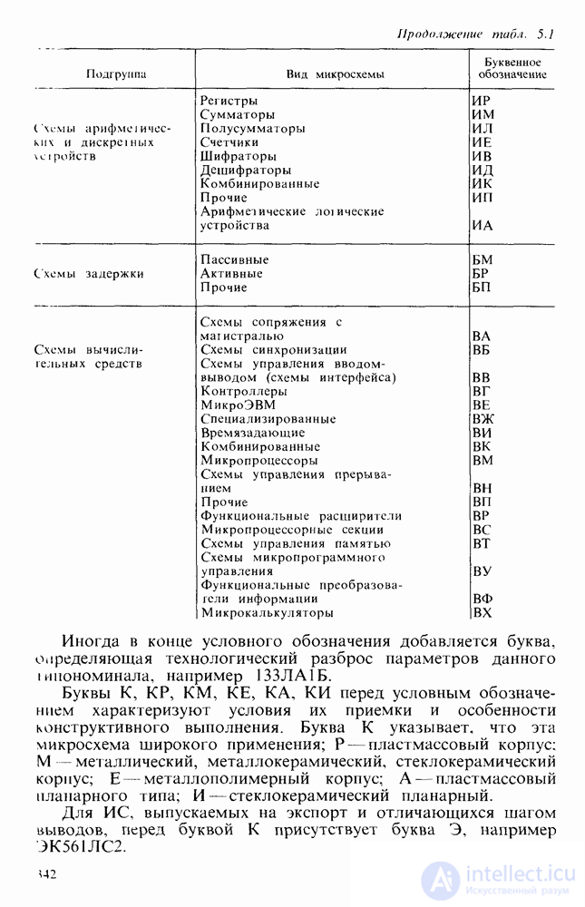
Sometimes a letter is added at the end of the designation indicating the technological parameter spread of a given sub-rating, for example 133LA1B.
The letters K, KR, KM, KE, KA, KI before the designation characterize their acceptance conditions and design features. The letter K indicates that the chip is for general use; R — plastic package; M — metal, metal-ceramic, or glass-ceramic package; E — metal-polymer package; A — plastic planar type; I — glass-ceramic planar.
For ICs manufactured for export and differing in lead pitch, the letter E is present before the letter K, for example E561LS2.
For chip-scale (unpackaged) ICs, the letter B is added before the series number, followed by a hyphen and a digit (1–6) indicating the modification of the design, for example: 1 — with flexible leads; 2 — with ribbon leads, etc.
Industry manufactures transistor arrays (several identical transistors in a single package), single-stage and multistage amplifiers.
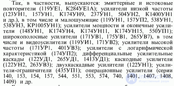
In particular, the following are produced: emitter and source followers  , low-frequency amplifiers
  and others, including low-noise ones
  , power amplifiers and output amplifiers
  , wideband amplifiers
  , including video amplifiers
  , high-frequency amplifiers
  , amplifiers with a logarithmic characteristic
  , differential amplifier stages
  , ZUD 1); cascode amplifiers
  , two-stage amplifiers
  , limiter amplifiers
  ; operational amplifiers (series 140, 153, 154, 157, 544, 551, 553, 574, 740, 1401, 1407, 1408, 1409), and others.
Catalogs and data sheets usually give the schematic diagrams of chips. However, for practical use one needs application guides, published in the form of industry standards. These give the pin connection diagrams of the chips and the recommended parameters of the external components. Without an application guide it is difficult to build a device with given parameters, because the schematic diagram is a combination of a large number of directly connected active and passive elements whose parameters are unknown.
In the simplest cases, such as the one shown in Fig. 5.2, a, a designer can connect the chip without additional reference materials. In doing so, they must know the fundamentals of amplifier-stage circuit design well and take into account that the passive networks present within the chip are designed on the basis of ensuring normal operation of the amplifier. Thus, when creating a unity-gain amplifier based on chip  , by means of appropriate external connections one can implement a source follower on transistor
  , similar to the one shown in Fig. 4.21, a. However, to obtain a lower output impedance, the circuit in Fig. 5.2, a uses transistor
  , connected in common-emitter configuration. The result is a unity-gain circuit with reduced output impedance, whose properties are similar to those of the stage in Fig. 4.49, c.


By connecting gate 10 of transistor  to pin 5 or 9, one can vary the DC voltage on the gate, and correspondingly the quiescent current and the maximum amplitude of the signal being amplified.
Other connection schemes for the chip are also possible. For this purpose, separate leads are provided from various elements.
The large number of pins on a chip expands its functional capabilities. The pins are designed so that external resistors, transformers, capacitors, LEDs, and other loads can be connected into individual circuits. This makes it possible to match the chip to the load; to change the operating modes of its amplifier stages; to remove negative feedback loops; to introduce additional feedback loops; to connect correcting networks that alter the amplifier's amplitude-frequency and phase-frequency response; and to use only the necessary number of the chip's elements.
However, obtaining specific parameter values and their reproducibility are, as a rule, guaranteed only when using the recommended connection schemes and external component ratings.
Figure 5.2, b shows the schematic diagram of a low-frequency amplifier of type  .
.
In it, when the external elements  are connected (Fig. 5.2, c), a preamplifier consisting of two common-emitter stages is formed using transistors
  . The output amplifier is built on transistors
  , and instead of a load resistor
  in the collector circuit of transistor
  , a transformer or other load can be installed. Through resistor
  , DC negative feedback is introduced, since the base current of transistor
  depends on this resistance and on
  . The capacitors
  reduce the depth of the negative feedback within the operating frequency range. Capacitors C3 and C5 provide correction of the frequency response, preventing the amplifier from losing stability (self-oscillation). The gain and other parameters depend on the external components
  over a 20 kHz band.
Powerful amplifiers are produced to whose output a substantial load can be connected. Thus, chip  provides an output power of
  , and so on. Table 5.2 gives some idea of the parameters of medium- and high-power amplifiers. The voltage gain of power-amplifier chips is usually not large (4–100). Therefore, they generally require a preamplifier, which is built using low-power chips. Because of the fairly high input impedance of the power chips, matching them to the preamplifiers presents no difficulty. In this case, the coupling capacitor values are determined as described in Section 5.1.
Table 5.2
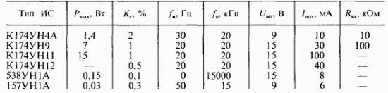
When obtaining power levels above 0.3 W, the chips need to be mounted on a heat sink (radiator), which carries away the heat dissipated in the IC. To obtain higher power levels, additional external transistors can be used.
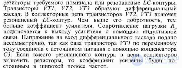
High-frequency and intermediate-frequency amplifier chips are, as a rule, built on the basis of differential amplifier stages, and to expand their functional capabilities the collector leads of the transistors are often left free, as, for example, in chip  (Fig. 5.3, a).
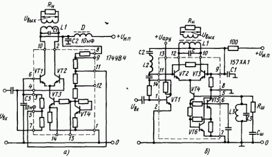
Fig. 5.3. Resonant high-frequency amplifier  (a) and high-frequency converter amplifier
This makes it possible to include in the collector circuit resistors of the required rating or resonant  tank circuits. Transistors
  form a differential stage. A resonant
  tank circuit is included in the collector circuits of transistors
  . The higher its quality factor, the greater the amplifier's gain. The load resistance
  is connected to the amplifier output by means of inductive coupling. The voltage applied to the input of the differential stage is asymmetric, since the base of transistor
  is connected to the supply, for AC purposes, through capacitor C3. If resistors are connected in the collector circuit instead of the resonant tank circuit, the gain will be constant over a wide frequency band.
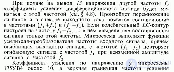
When a voltage of a different frequency  is applied to pin 13, the gain of the differential stage will vary at this frequency (see section 4.8). The signals will multiply together, and components at frequencies
  will appear in the output current spectrum. If the resonant
  tank circuit is tuned to frequency
  , then only the signal component at this frequency will be "selected" in it. The chip performs the function of a frequency converter-amplifier for the input signal, and the envelope of the output signal at that frequency reproduces the envelope of the signal at frequency
  , with the amplitude of the signal at frequency
  remaining unchanged.
The voltage gain of chip  is about 10, and the upper cutoff frequency of amplification (the frequency at which the guaranteed amplitude
  is maintained) is 150 MHz.
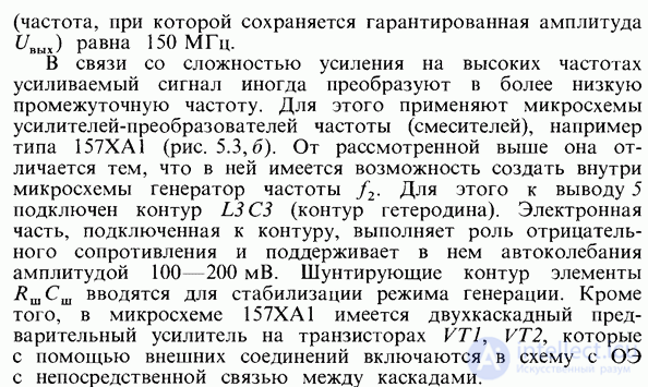
Because of the difficulty of amplification at high frequencies, the signal being amplified is sometimes converted to a lower intermediate frequency. For this purpose, frequency-converter (mixer) amplifier chips are used, for example of type  (Fig.
(Fig.  ). It differs from the one discussed above in that it is possible to create a frequency generator
  inside the chip. For this purpose, a tank circuit
  (the local-oscillator circuit) is connected to pin 5. The electronic part connected to the tank circuit acts as a negative resistance and sustains self-oscillations of amplitude
  in it. The elements
  that shunt the tank circuit are introduced to stabilize the oscillation mode. In addition, chip
  contains a two-stage preamplifier on transistors
  , which are connected via external connections in a common-emitter configuration with direct coupling between the stages.
The complexity, degree of integration, and functional capabilities of integrated amplifiers are continuously increasing. The purpose of this is to make it possible to build large blocks of an electronic device on the basis of a single chip.
The first integrated operational amplifier, the µA702, was developed in 1963 by Robert Widlar, an employee of Fairchild Semiconductor. The device contained only 9 transistors, but cost as much as 300 dollars, which meant it could only be used in military applications. But overall, this was a huge step forward, one of the greatest breakthroughs in electronics.
Already in 1965, Robert Widlar designed the µA709 operational amplifier, which was much cheaper to manufacture — only 10 dollars. Even that price did not allow it to be used in consumer electronics, but it was quite acceptable for industrial automation and similar applications.
In 1967, Widlar moved to National Semiconductor, where under his leadership the LM101 was developed, which had better characteristics. In 1968, Fairchild released the µA741, which had internal frequency compensation, making its operation even more stable — operational amplifiers with internal compensation are not prone to self-oscillation.
As already mentioned, the main purpose of an operational amplifier is to perform mathematical operations on analog variables represented by voltages (summation, integration, multiplication, etc.). But it later turned out that the op-amp is a very versatile element, and its applications are practically limitless: signal amplification, active frequency filters, oscillators, comparators, and much more.
Nowadays operational amplifiers are produced in such quantities that it is simply impossible to do without them. Moreover, the price of these electronic products is in some cases very low, while their capabilities are quite high. Several operational amplifiers can now be housed in a single package at once, and micro-power consumption together with a very low level of intrinsic noise bring real amplifiers close to ideal ones. All this allows operational amplifiers to be used even in professional audio equipment (multichannel mixers), making them simply indispensable.
Of course, the history of the emergence and development of operational amplifiers is much longer and, probably, more interesting, but for now let us limit ourselves to this information.
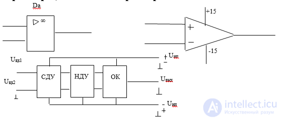
SDA — symmetric differential amplifier. Its purpose is to suppress zero drift as much as possible. NDA — non-symmetric differential amplifier. Needed to connect the output to the common point. CC — common-collector configuration. Needed to reduce the output impedance and increase the power of the output signal. Operational amplifiers generally allow an output current on the order of several milliamps. The dependence of the op-amp's output voltage on the input voltage is called the transfer characteristic. In this case, a real operational amplifier has a nonzero output voltage at zero input voltage. This voltage is the offset voltage. This is not a sign of drift, but is caused by the asymmetry of a particular sample of the operational amplifier arising during its manufacture.
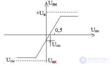
For real devices, the offset voltage amounts to tens or hundreds of millivolts. Using trim resistors, this zero offset can be compensated.
Since the voltage gain of a real operational amplifier can range from tens of thousands to several million, the operating range of input voltage variation is very small. Negative feedback is used to widen it.
The main parameters of the input circuits of an operational amplifier are as follows:
input resistance, input currents at both inputs, the difference and drift of the input currents, the maximum differential input resistance, the maximum common-mode input voltage, common-mode error, and so on.
The output parameters are: output resistance, maximum output voltage, output current (load current).
How operational amplifiers are denoted on circuit diagrams
Like all electronic components, operational amplifiers are denoted on diagrams using standard graphic symbols. The symbols can be quite varied, although, in general, they denote the same thing. When first becoming familiar with circuits using operational amplifiers, doubts arise: what if I do something wrong, what if everything just burns out.
If we disregard the internal structure of operational amplifiers, which, incidentally, looks quite complex at first glance (such are the traditions of integrated electronics), externally op-amps look simple and logical. The following description concerns precisely the external leads and their use in various circuits.
A modern operational amplifier generally has two inputs, one output, and two leads for connecting power. This is the minimal "gentleman's" set. In addition to the leads mentioned, there may be leads for connecting frequency-compensation elements and leads for balancing (trimming the output to zero). Various symbols for operational amplifiers are shown in Figure 1. Let us examine them in as much detail as possible.
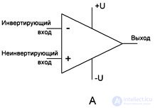
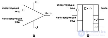
Figure 3.
In Figures 1a and 1b, the operational amplifier's package is shown as an isosceles triangle. Yes, this is nothing more than the chip's package. On the left side are two inputs: the inverting input (denoted by a "minus" sign or a small circle) and the non-inverting input (denoted by a "plus" sign or simply drawn without a circle). Note: if the diagram is drawn according to "good style" conventions, all inputs are located on the left and outputs on the right of the element in question. Auxiliary leads, such as for compensation or power, may be placed anywhere.
And right there, in the right-hand corner of the triangle, is the lead labeled "Output," while above and below are shown the leads for connecting power, most often dual-polarity. To avoid overloading or cluttering the diagram, the power leads are most often not shown. Their connection is simply indicated in notes accompanying the diagram.
The package of an operational amplifier can be depicted as a rectangle, as shown in Figure 1c. All the other parts of this figure are the same as in the case of the triangular package.
Operational amplifier packages
Modern semiconductor technology has reached such a level of perfection that the number of semiconductor structures in a single package simply cannot be counted. It is enough to recall modern microprocessors, in which the number of transistors is measured in the billions. Therefore, placing several operational amplifiers, each containing only a few dozen transistors, in a single package is actually a very simple matter.
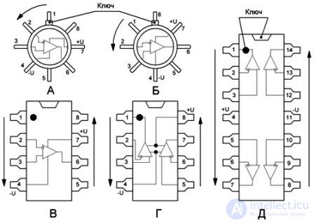
Figure 4.
The arrangement of the leads of operational amplifiers of various types within the same packages is identical, which makes it very easy to replace them, especially when the operational amplifiers are installed in sockets. But, at the same time, an operational amplifier of a single type can be manufactured in completely different packages. This variety is required under conditions of mass and large-scale production, mainly for the convenience of designing printed circuit boards and the entire construction of the electronic device.
Figure 3 shows operational amplifiers made in DIP8 and DIP14 packages.
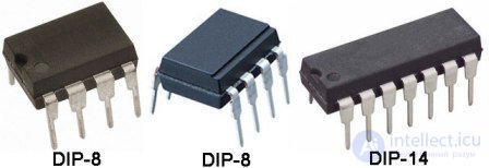
Figure 5.
Figure 4 shows an operational amplifier of type 4558 in a SIP-8 package — a single-row, eight-pin package.
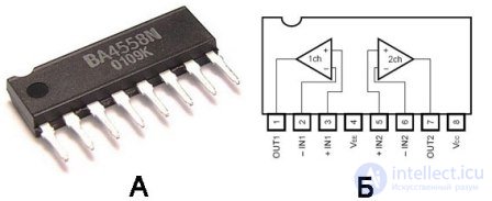
Figure 6.
At present, operational amplifiers in surface-mount packages — SMD — are gaining increasing popularity.
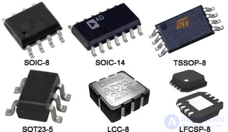
Figure 7.
To better understand the principles of building circuits using operational amplifiers, the concept of an ideal operational amplifier is often used. What exactly is so ideal about it, what are its wonderful properties? There aren't that many of them, but they all tend either to zero or, on the contrary, to infinity. But an operational amplifier behaves this way only when it is not covered by feedback (FB) and has no external connections at all.
In this article we will try to describe feedback and some connection schemes for operational amplifiers without resorting to cumbersome mathematical formulas involving integrals. But some very simple and understandable ones, at about an eighth-grade level, which will help convey the general idea, cannot be avoided.
Gain
With such an "unrestrained" gain, it is enough to apply just a few microvolts to its inputs (for example, mains-induced pickup) to obtain an output voltage close to the supply voltage of 15V. Such a state indicates that the output is saturated.
It is worth recalling here the same kind of state in transistors. Naturally, in this form no amplification at all is achieved. Therefore, real operational amplifiers are always covered by negative feedback, which will be discussed a little further below.
Although it should be noted that operational amplifiers are quite often used without feedback, and in some cases even with positive feedback. This kind of use is found in comparators — devices for precisely comparing analog signals. Comparators are produced as dedicated chips and are also included within other chips. It is enough to recall the legendary integrated timer NE555, which contains two comparators inside it.
A fairly recent history
At one time, domestic [Soviet/Russian] electronics industry also mastered the production of operational amplifiers. The first operational amplifier was the K1UT401A(B), later renamed K140UD1 with the same letters at the end. As it happens, being an almost exact copy of its American counterpart, the UA702, the version with the letter A, at a supply voltage of ±6V, had a gain in the range of 500...4500, while the version with the letter B (±12V) had a gain of 1500...13000.
By today's standards this is simply laughable, but nevertheless, these archaic amplifiers can still occasionally be encountered. But even with such "small" gains, it was impossible to do without negative feedback.
And it was precisely the emergence of integrated operational amplifiers that introduced this versatile component into industrial, consumer, and hobbyist circuits. After all, you must agree that an operational amplifier built on vacuum tubes, or even a transistor version, could not be used anywhere except in defense-purpose analog computers.
Inputs and outputs of operational amplifiers
An operational amplifier has two inputs and one output, and, of course, two leads for supplying power. This is the minimal, vitally necessary set of leads. This is exactly what most modern operational amplifiers have. At one time there used to be leads for connecting frequency-compensation and balancing elements.
Power is most often dual-polarity with a center point, which makes it possible to amplify DC voltage. In this case, it is customary to consider that the frequency range of operational amplifiers starts from 0 Hz, while the upper frequency is limited both by the type of operational amplifier itself, its internal circuit design and the type of transistors used, and by the way it is connected.
The bandwidth of an ideal operational amplifier extends from direct current to infinity. Its speed, or the slew rate of the output signal, also tends toward infinity. But we will not consider this question for now.
What an operational amplifier amplifies
The output voltage of an operational amplifier is proportional to the difference between the voltages at its inputs. In this case, the absolute level of the signals, as well as their polarity, does not play any particular role. Only the difference matters. And since all the terminology in electronics comes from English, it's worth recalling the word "different," which translates as dissimilar, difference-related (Multitran dictionary), and amplifiers operating on this principle are called differential amplifiers.
What an operational amplifier does not amplify
Here one can also recall another wonderful property of operational amplifiers — common-mode signal rejection: if the same signal is applied to both inputs, it will not be amplified. This property is used when transmitting a signal over long wires: the useful signal has a different phase, while the interference signal is the same at both inputs.
What can be obtained at the output of an operational amplifier
The output impedance of an ideal operational amplifier tends toward zero, which theoretically makes it possible to obtain an output signal of any magnitude, even infinite. In reality, the output voltage of a real operational amplifier is limited by the supply voltages: if the dual-polarity supply voltage is, for example, ±15V, then obtaining +20 or -25 at the output is simply impossible.
This concerns the amplification of DC voltages. In the case of amplifying, say, a sine wave, the output should likewise be a sine wave whose amplitude does not exceed the supply voltage.
The input and output voltages cannot be higher than the supply voltage. For example, with a supply of ±15V, the output voltage is 0.5...1.5V lower. But some modern chips make it possible to obtain an output and input voltage equal to the supply voltage. This property is denoted in datasheets as Rail-to-Rail, literally meaning "from rail to rail." This property should be taken into account when choosing an operational amplifier.
Input resistance
The input resistance of both inputs of an operational amplifier is very high and lies in the range of hundreds of megohms, and in some cases even gigohms. For comparison: the K1UT401 mentioned above had an input resistance of only a few tens of kilohms.
The input resistance, of course, does not reach infinity as in an ideal operational amplifier, but it is nevertheless so high that it has no effect on the levels of the input signals. From this we can conclude that no current flows into the inputs. This is one of the main principles used in the calculation and analysis of circuits based on operational amplifiers. For now, it just needs to be remembered.
The last statement applies directly to operational amplifiers themselves. Such high input resistance is inherent in the operational amplifier itself, but the input resistance of various circuits built on its basis can be much lower. This fact should always be kept in mind. Now pay close attention, as the account of the most important thing is about to begin.
Negative feedback (NFB)
NFB is nothing other than a connection from the output to the input, in which a portion of the output is subtracted from the input signal. Such a connection leads to a reduction in gain. In contrast to NFB, there is positive feedback (PFB), which, on the contrary, adds a portion of the output to the input signal. Such connections are used not only in electronic engineering but in many other cases as well, for example in mechanics. The effect of these feedback loops can be characterized as follows: negative feedback leads to stability of the system's operation, while positive feedback leads to its instability.
As applied to the operational amplifiers under discussion, negative feedback makes it possible to set the gain with sufficient accuracy, and also leads to many other qualitative and even pleasant improvements to the circuit. But first we need to understand how negative feedback works. As an example, let us consider a circuit that can be found in any textbook on automatic control.
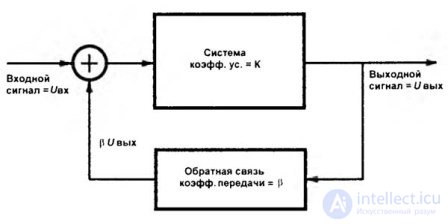
Figure 1.
The output signal U.out. from the output passes to the summing device (a circle with a plus sign inside) through the negative-feedback network with a transfer coefficient β, which in this case is less than one. If this coefficient is made greater than one, which is technically possible, then instead of amplification of the signal we would get its attenuation. But for now let us assume that amplification is indeed what we need.
A break in the feedback loop is simply a disaster
If the feedback loop is broken, the voltage at the output of the operational amplifier will become U.out.=K*U.in. Theoretically, an enormous value. In reality, it will be limited by the supply voltage. This has already been mentioned earlier. A similar example: if this were an electric motor with speed stabilization (also a form of feedback), it would simply run away as fast as possible. In such a case, the system is said to have gone "out of control."
Passing through the negative-feedback network, the output signal is attenuated by an amount β*U.out. Therefore, only (U.in.-β*U.out.) reaches the amplifier input through the summer. The "minus" sign indicates that the feedback is negative. After passing through a device with gain K, the output becomes U.out.= K*(U.in.-β*U.out.). In turn, the gain of the entire system K.gain=U.out./U.in., and it turns out that U.out.=K*
After some transformations, the following result can be obtained: K.gain=U.out./U.in.= K*U.in./U.in.*(1+ K*β)= K/(1+ K*β)
All these transformations led to the fairly simple formula K.gain=K/(1+ K*β). If we assume that K is sufficiently large (and in the case of an operational amplifier this is indeed so), then the "1" in the parentheses won't make much difference and can be dropped, giving the formula the following form:
K.gain=1/β
The resulting formula (which is, in fact, the whole reason for erecting this fence of formulas in the first place) lets us state that the transfer coefficient of an operational amplifier in a feedback circuit does not in any way depend on the gain of the operational amplifier itself, but is determined solely by the parameters of the feedback loop — specifically, its transfer coefficient β. Nevertheless, the higher the gain of the operational amplifier itself, the more accurate the results given by this formula, and the more stable the circuit's operation.
References: M.H. Jones, Electronics — A Practical Course, Moscow: Technosphere, 2006. – 512 pp. ISBN 5-94836-086-5

Comments