
Lecture
The symbols used for switches and buttons in electrical diagrams vary depending on their type (momentary, latching, multi-position switches, and so on). Here are the main symbols:
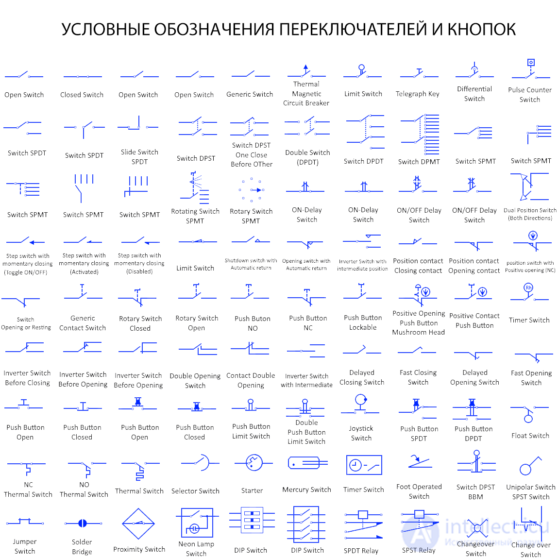
General switch symbol
This is the symbol for a universal switch in the open state.
Open switch
This is the general symbol for an open switch. A switch is a component that can break or complete a circuit. An open switch represents a break in the circuit and stops current from flowing through it.
Closed switch
This is the general symbol for a closed switch. A closed switch means the circuit is complete and current can flow through it.
Thermal-magnetic circuit breaker
This is the symbol for a thermal-magnetic circuit breaker. It includes both electromagnetic and thermal tripping. During huge current surges, the electromagnet instantly breaks the circuit with no delay at all. But its bimetallic strip provides a slight delay when the current exceeds its rated limit.
Limit switch
This symbol represents a limit switch. It is actuated by the mechanical parts of any machine used in control systems. It is triggered by other objects or machine parts when they come into contact with its actuator.
Telegraph key
The telegraph key is represented by this symbol. It is a special electrical switch designed for transmitting text messages in Morse code. It connects and disconnects the circuit, creating pulses of varying length called "dots" and "dashes."
Differential switch
Differential circuit breakers operate based on the difference between the current in the phase line and the current in the neutral line. If there is any current difference (due to a fault current), it breaks the circuit.
Pulse-counter switch
The actuator of this switch is controlled by a pulse counter. When the pulse counter reaches a fixed value, the switch activates and switches the circuit connected to it.
SPDT switch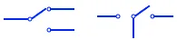
This is the symbol for a single pole double throw (SPDT) switch. This type of switch has three terminals, one of which is common. The common terminal is connected to one of the other two terminals.
SPDT slide switch
A slide switch has a slider that moves back and forth to turn current in the circuit on and off. The symbol shown is for an SPDT slide switch, also known as a single pole double throw switch.
DPST switch
DPST stands for double pole single throw switch. It has two poles, meaning two different circuits can be connected to it, and single throw means it has only one ON position (closed circuit). It either turns two circuits on or off at the same time.
DPST switch, one pole closes before the other
This is also a DPST switch, but this type has one modified pole that closes (makes contact) before the other during the closing action. These are used in special cases where one connection needs to be made before the other.
DPDT switch
DPDT stands for double pole double throw. It is essentially two SPDT switches joined by a common lever. A DPDT switch can switch two different circuits simultaneously. In either of its two positions, each circuit makes a tight connection with separate terminals.
DPMT switch
DPMT stands for double pole multi throw. This switch has two poles, meaning it can switch two independent circuits. Each circuit can be switched to several terminals.
SP4T switch
This is the symbol for a single pole, 4-throw switch. It has 4 positions and can switch a single circuit by connecting it to any of the 4 terminals.
Rotary switch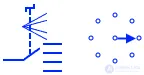
This is the symbol used for a rotary switch. It has a knob that rotates about its axis and switches the common terminal to any of the output terminals. Rotary switches can have multiple levels (poles) for switching several separate circuits and multiple throws.
Time-delay closing switch
A time-delay closing switch switches instantly from the ON (closed) position to the OFF (open) position. But when switching from the OFF position to the ON position, a certain delay is required. The symbolic representation of a time-delay closing switch is shown above.
Time-delay closing/opening switch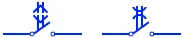
This type of switch has a time-delay function for every switching action. Whether switching from ON to OFF or from OFF to ON, in both cases the switching occurs after a certain time delay.
General-purpose push-button switch
This is the symbol for a general-purpose single pole single throw push-button switch. It has an actuator that turns the circuit on and off when pressed.
Rotary switch, closed
This is the symbol for a rotary switch in the closed (ON) position. It is a single pole switch in the closed-contact position. It has no automatic return position.
Rotary switch, "open"
This is the symbol for a rotary switch in the open (OFF) position.
NO button
This is a normally open (NO) button. It is normally in the open (OFF) position. Pressing the button switches it to the ON (closed) position, but releasing the button returns the switch to the OFF (open) position.
NC button
This is a normally closed button, which normally stays closed (ON position). It switches to the OFF position when the button is pressed, but returns to the CLOSED position after being released.
Button with a lock
This is the symbol for a button with a locking function. It automatically returns to its normal position, but it can be locked in a desired position.
Mushroom-head, positive-opening button
This is a mushroom-head button. It is a positive-opening switch, meaning its contacts are open when the device is in the corresponding open position.
Positive-closing button
This is also a button with a positive closing contact (closed position). Its contact closes when the switch position corresponds to the switch's closed position.
Timer switch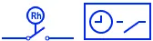
This is the symbol for a timer switch. It mainly closes and opens the contact when the timer runs out. The timer is set using a mechanical clockwork mechanism. It provides a time delay for certain applications.
Time-delay closing switch
This is the symbol for a switch whose contact does not close immediately, but with a slight delay.
Quick-closing switch
This symbol represents a quick-closing switch. This switch closes (turns on) instantly after its position is switched.
Time-delay opening switch
This is a switch with a delayed opening action. When its position switches from ON to OFF, its contacts remain closed for a certain time longer.
Quick-opening switch
This switch opens its contacts instantly when switched, thereby creating a quick-break situation.
Push-to-make switch
This symbol represents a push-button switch in the open position, also known as a "push-to-make" switch. Pressing and holding the button manually closes its contact into the ON position. Once the button is released, the switch returns to the open state.
Push-to-break switch
This switch is normally in the closed state, i.e., the circuit is complete. If the button is pressed and held, the circuit is broken. Once the button is released, it returns to its normal closed state.
Push-button limit switch
This is a push-button limit switch. Limit switches are actuated by the movement of mechanical machine parts or other objects, etc. It switches circuits that control other parts of the machine.
Push-button double-pole limit switch
This is also a limit switch, but it is double pole, i.e., it controls two separate circuits. This type of switch opens one circuit and closes the other.
Joystick switch
A joystick is a switch with a lever or handle connected to a base. Directional movement of the handle connects the switch's various terminals. It is used in game controllers, as well as in industrial cranes and trucks.
SPDT button
This is a single pole double throw button. This switch has no open position. It makes contact (ON state) in both positions. Pressing and holding the button switches the circuit to the other terminal. Releasing the button returns the contact to its original position.
DPDT button
This is a double pole double throw switch. It switches two separate circuits, and pressing the button opens one circuit while closing the other. Releasing the button also reverses the switching.
Float switch
A float switch is a switch that controls a circuit or machine inside a tank filled with liquid. It detects the liquid level and turns on or off as the liquid level rises or falls.
Thermal switch
A thermal switch is a temperature-dependent switch that switches the circuit when a set temperature is crossed. However, it returns to its normal position once the temperature returns to normal.
NC thermal switch
This is a normally closed thermal switch, which is in the ON (closed) position at room temperature. When the temperature rises above a fixed point, it opens the circuit. When the temperature falls back below that point, it closes the circuit.
NO thermal switch
This is also a thermal switch, which is normally open at room temperature. A rise in temperature switches the contact to the ON position, while a drop switches it to OFF.
Selector switch
A selector switch is a rotary switch with two or more positions. It can switch one or more circuits at the same time.
Starter
Also known as an electronic fluorescent starter, it is used to smoothly start a fluorescent lamp by preheating the cathode and delivering a controlled pulse to the lamp to initiate glow.
Mercury switch
A mercury switch has mercury inside a sealed vessel between two switch terminals. The movement of the mercury closes and opens the circuit as the vessel is tilted. Mercury is a conductor and connects the terminals when it touches them. A mercury switch can be used wherever there is motion, such as tilting, rotation, etc.
Foot switch
This symbol represents a foot or pedal switch. It is a single pole switch that controls a circuit or motor, typically used to control heavy equipment. It has a very rugged design since it is operated by foot.
DPST BBM switch
This is a double pole single throw switch with a break-before-make (BBM) mechanism. It switches two circuits, but it first opens (breaks) one circuit and then closes (makes) the other.
Contactless switch
A proximity sensor is a sensor that detects an object at close range. It is a contactless sensor. Whenever an object comes within its range, it switches and the corresponding circuit is activated. This circuit can be an alarm, a counter, or any type of logic circuit.
Neon lamp switch
This is a simple single pole single throw switch with a neon lamp. The neon lamp acts as an indicator, showing that current is flowing through the switch.
DIP switch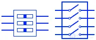
DIP stands for dual in-line package. It is made by packaging several switches together into a dual in-line package (DIP). Thanks to its compact size, it is used on printed circuit boards (PCBs).

Comments