You get a bonus - 1 coin for daily activity. Now you have 1 coin

Electrical Elements as a Conceptual Abstraction: Types

Lecture


Electrical elements are conceptual abstractions representing idealized electrical components, such as resistors, capacitors, and inductors, used in the analysis of electrical networks. All electrical networks can be analyzed as a number of electrical elements interconnected by wires. Where the elements correspond roughly to real components, the representation may take the form of a schematic diagram or electrical circuit. This is called a lumped-element circuit model. In other cases, infinitesimal elements are used to model the network in a distributed-element model.

These ideal electrical elements represent real, physical electrical or electronic components, but they do not exist physically, and are assumed to have ideal properties, whereas actual electrical components have less-than-ideal properties, some degree of uncertainty in their values, and some degree of nonlinearity. To model the non-ideal behavior of a real circuit component, it may be necessary to combine several ideal electrical elements in order to approximate its function. For example, an inductor circuit element is assumed to have inductance but no resistance or capacitance, while a real inductor, a coil of wire, has some resistance in addition to its inductance. This can be modeled by means of an ideal inductive element in series with a resistance.

Analyzing a circuit using electrical elements is useful for understanding many practical electrical networks that use components. By analyzing the network's response affected by its individual elements, one can estimate how the real network will behave.

Types of Elements

Circuit elements can be classified in different categories. One is by how many terminals they need to connect them to other components:

  • One-port elements - these are the simplest components, which have only two terminals for connection. Examples are resistors, capacitors, inductors, and diodes.
  • Multi-port elements - these have more than two terminals. They connect to external circuits through several pairs of terminals called ports. For example, a transformer with three separate windings has six terminals and can be idealized as a three-port element; the ends of each winding are connected to a pair of terminals, which constitute a port.
    • Two-port elements - these are the most common multi-port elements, which have four terminals consisting of two ports.

Elements can also be divided into active and passive:

  • Active elements, or sources - these are elements which can source electrical power; examples are voltage sources and current sources. They can be used to represent ideal batteries and power supplies.
    • Dependent sources - these are two-port elements with a voltage or current source that is proportional to the voltage or current on a second pair of terminals. They are used in modeling the gain of components such as transistors, vacuum tubes, and operational amplifiers.
  • Passive elements - these are elements that have no source of energy; examples are diodes, resistors, capacitors, and inductors.

Another distinction is between linear and nonlinear:

  • Linear elements - these are elements in which the constitutive relation, the relationship between voltage and current, is a linear function. They obey the principle of superposition. Examples of linear elements are resistance, capacitance, inductance, and dependent linear sources. Circuits with only linear elements, linear circuits, do not cause intermodulation distortion, and can be readily analyzed using powerful mathematical methods such as the Laplace transform.
  • Nonlinear elements - these are elements in which the relationship between voltage and current is a nonlinear function. An example is a diode, in which the current is an exponential function of the voltage. Circuits with nonlinear elements are more difficult to analyze and design, often requiring circuit modeling computer programs such as SPICE.

One-Port Elements

Only nine types of elements (the memristor is not included), five passive and four active, are needed to model any electrical component or circuit. Each element is defined by a relationship between the network's state variables: current, ; voltage, ; charge, ; and magnetic flux, . Electrical Elements as a Conceptual Abstraction: TypesElectrical Elements as a Conceptual Abstraction: TypesElectrical Elements as a Conceptual Abstraction: TypesElectrical Elements as a Conceptual Abstraction: Types

  • Two sources:
    • A current source, measured in amperes, produces a current in a conductor. It affects the charge according to the relation.Electrical Elements as a Conceptual Abstraction: Types
    • A voltage source, measured in volts, produces a potential difference between two points. It affects the magnetic flux according to the relation.Electrical Elements as a Conceptual Abstraction: Types

Electrical Elements as a Conceptual Abstraction: Typesin these relations does not necessarily represent anything physically meaningful. In the case of a current generator, , the time integral of the current, represents the amount of electric charge physically supplied by the generator. Here there is a time integral of the voltage, but whether or not it represents a physical quantity depends on the nature of the voltage source. For a voltage generated by magnetic induction, it makes sense, but for an electrochemical source, or a voltage that is the output of another circuit, no physical meaning is attached to it.Electrical Elements as a Conceptual Abstraction: TypesElectrical Elements as a Conceptual Abstraction: Types

Both of these elements are necessarily nonlinear elements. See #Nonlinear Elements below.

  • Three passive elements:
    • Resistance, measured in ohms, produces a voltage proportional to the current flowing through the element. It relates voltage and current according to the relation.Electrical Elements as a Conceptual Abstraction: TypesElectrical Elements as a Conceptual Abstraction: Types
    • Capacitance, measured in farads, produces a current proportional to the rate of change of the voltage across the element. It relates charge and voltage according to the relation.Electrical Elements as a Conceptual Abstraction: TypesElectrical Elements as a Conceptual Abstraction: Types
    • Inductance, measured in henries, produces a magnetic flux proportional to the rate of change of the current through the element. It relates flux and current according to the relation.Electrical Elements as a Conceptual Abstraction: TypesElectrical Elements as a Conceptual Abstraction: Types
  • Four abstract active elements:
    • A voltage-controlled voltage source (VCVS) generates a voltage based on another voltage relative to a specified gain factor (it has infinite input impedance and zero output impedance).
    • A voltage-controlled current source (VCCS) generates a current based on a voltage elsewhere in the circuit, relative to a specified gain, used for modeling field-effect transistors and vacuum tubes (it has infinite input resistance and infinite output impedance). The gain is characterized by transconductance, which has units of siemens.
    • A current-controlled voltage source (CCVS) generates a voltage based on an input current elsewhere in the circuit, relative to a specified gain (it has zero input impedance and zero output impedance). Used for modeling transistors. The gain is characterized by transimpedance, which has units of ohms.
    • A current-controlled current source (CCCS) generates a current based on an input current and a specified gain factor. Used for modeling bipolar transistors (it has zero input impedance and infinite output impedance).

These four elements are examples of two-port elements.
Nonlinear Elements

Electrical Elements as a Conceptual Abstraction: Types

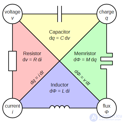
Conceptual symmetries of the resistor, capacitor, inductor, and memristor.

In reality, all circuit components are nonlinear and can only be approximated as linear within a certain range. In order to describe passive elements more accurately, their constitutive relation is used instead of simple proportionality. From any two circuit variables, six constitutive relations can be formed. From this it can be assumed that there is a theoretical fourth passive element, since there are only five elements in total (not including the various dependent sources) found in linear network analysis. This additional element is called a memristor. It has meaning only as a time-dependent nonlinear element; as a time-independent linear element it reduces to a regular resistor. Consequently, it is not included in linear time-invariant (LTI) circuit models. The constitutive relations of the passive elements are defined as follows:

  • Resistance: the constitutive relation is defined as .Electrical Elements as a Conceptual Abstraction: Types
  • Capacitance: the constitutive relation is defined as .Electrical Elements as a Conceptual Abstraction: Types
  • Inductance: the constitutive relation is defined as .Electrical Elements as a Conceptual Abstraction: Types
  • Memristance: the constitutive relation is defined as .Electrical Elements as a Conceptual Abstraction: Types

where is an arbitrary function of two variables.Electrical Elements as a Conceptual Abstraction: Types

In some special cases the constitutive relation simplifies to a function of one variable. This is the case for all linear elements, but also, for example, for the ideal diode, which from the point of view of circuit theory is a nonlinear resistor, has a constitutive relation of the form. Both independent voltage and independent current sources can be regarded as nonlinear resistors under this definition.Electrical Elements as a Conceptual Abstraction: Types

The fourth passive element, the memristor, was proposed by Leon Chua in a 1971 paper, but a physical component demonstrating memristance was not created until thirty-seven years later. It was reported on April 30, 2008, that a working memristor had been developed by a team of specialists at HP Labs led by scientist R. Stanley Williams. With the advent of memristors, every pairing of the four variables could be related to one another.

There are also two special nonlinear elements which are sometimes used in analysis but are not the ideal analogue of any real component:

  • Nullator: defined asElectrical Elements as a Conceptual Abstraction: Types
  • Norator: defined as an element that imposes no constraints on voltage and current at all.

They are sometimes used in models of components with more than two terminals: transistors, for example.

Two-Port Elements

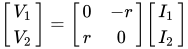
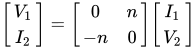
All of the above are two-terminal, or one-port, elements, with the exception of the dependent sources. There are two lossless, passive, linear two-port elements that are commonly introduced in network analysis. Their constitutive relations in matrix form are as follows:

Transformer
Electrical Elements as a Conceptual Abstraction: Types

Gyrator

Electrical Elements as a Conceptual Abstraction: Types

The transformer maps the voltage at one port to the voltage at the other in the ratio n. Meanwhile, the currents between the same two ports are mapped by 1/n. The gyrator, on the other hand, maps the voltage at one port to the current at the other. Likewise, currents are transformed into voltages. The quantity r in the matrix is in units of resistance. The gyrator is a necessary element in analysis because it is non-reciprocal. Networks built from basic linear elements alone are required to be reciprocal and therefore cannot by themselves represent a non-reciprocal system. It is not necessary, however, to have both a transformer and a gyrator. Two gyrators in cascade are equivalent to a transformer, but a transformer is usually retained for convenience. The introduction of the gyrator also makes either capacitance or inductance redundant, since a gyrator terminated with one of them at port 2 will be equivalent to the other at port 1. However, the transformer, capacitor, and inductor are generally retained in analysis, since they are the ideal properties of the basic physical components of the transformer, inductor, and capacitor, whereas in a practical gyrator they must be implemented as an active circuit.

Below are examples of representing components by means of electrical elements.

  • As a first approximation, a battery is represented by a voltage source. A more refined model also includes a resistance in series with the voltage source, to represent the internal resistance of the battery (which causes the battery to heat up and its voltage to drop during use). A current source in parallel can be added to represent its leakage (which discharges the battery over an extended period of time).
  • As a first approximation, a resistor is represented by a resistance. A more refined model also includes a series inductance, to represent the effect of its leads' inductance (resistors made in the form of a coil have more significant inductance). A parallel capacitance can be added to represent the capacitive effect of the resistor's leads being close to one another. A wire can be represented as a very-low-value resistor.
  • Current sources are more often used when representing semiconductors. For example, as a first approximation, a bipolar transistor can be represented as a variable current source controlled by an input current.

Comments

To leave a comment

If you have any suggestion, idea, thanks or comment, feel free to write. We really value feedback and are glad to hear your opinion.
To reply

Lectures and tutorial on "Electronics, Microelectronics, Element Base"

Terms: Electronics, Microelectronics, Element Base