
Lecture
In electrical circuit diagrams, diodes are represented in several ways, depending on their type and purpose.
Here are some of the main schematic symbols for diodes:
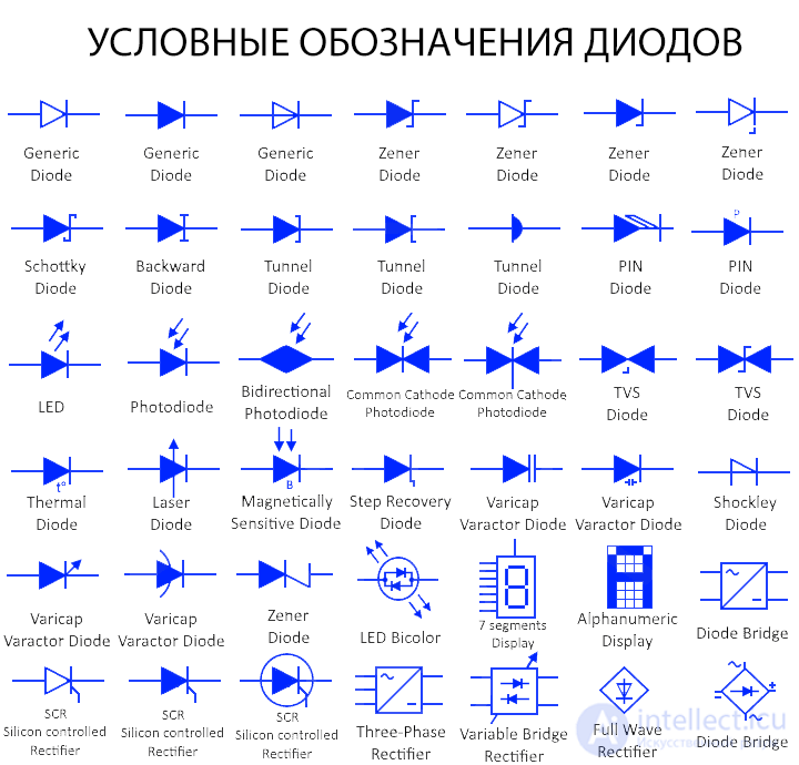
Ordinary diode
This symbol represents a diode or rectifier diode. It is an electronic component made from a semiconductor that allows current to flow in one direction and blocks it in the reverse direction.
Zener diode
A Zener diode is a type of diode that allows current to flow in both the forward and reverse directions, but when the reverse voltage reaches the breakdown voltage, known as the Zener voltage.
Schottky diode
This type of diode is made from a small junction between an N-type semiconductor and a metal. It has no PN junction, unlike ordinary diodes. Because of this, it has a very low forward voltage drop and fast switching, since there is no capacitive junction (PN junction).
Backward diode
This is a type of diode that behaves as a tunnel diode under forward bias and as a Zener diode under reverse bias. However, its tunneling effect and Zener breakdown voltage are significantly reduced. It is used to rectify low-voltage signals (from 0.1 to 0.6 V).
Tunnel diode
This type of diode is made from a heavily doped P&N semiconductor that operates on the principle of the tunneling effect . Tunneling is the phenomenon of electrons escaping across the PN junction due to heavy doping. The tunnel diode has a negative-resistance region, where current decreases as voltage increases, and it operates in that region.
PIN diode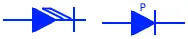
This is a three-layer diode, where PIN stands for P-layer, I-layer, and N-layer. The intrinsic semiconductor layer ' I ' is located between the heavily doped P layer and the N-type semiconductor. The I-layer blocks high voltage under reverse bias. Due to their poor reverse recovery time, they are not used in high-frequency applications.
LED – light-emitting diode
A light-emitting diode (LED) is a type of pn-junction diode that emits light when forward-biased. It converts electrical energy into light energy, and the color of the light depends on the energy band gap of the semiconductor.
Bicolor LED
This is a type of LED that has two different colored LEDs connected in antiparallel inside a single package. It can emit two different colors depending on the polarity. Reversing the direction of current activates the LED in the other color.
Photodiode
A photodiode converts light energy into electrical energy. When light strikes the PN junction, it creates an electron-hole pair, which flows out as an electric current. This symbol denotes a photodiode.
Bidirectional photodiode
An ordinary photodiode is designed to operate only under reverse bias. This type of photodiode operates in both directions.
Common-cathode photodiode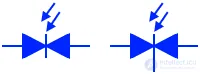
This type of photodiode is made of two diodes in a single package with one common terminal — the cathode.
TVS diode
A transient voltage suppression diode is a type of diode used to suppress high-voltage surges. It is used to protect a circuit under reverse bias (unidirectional TVS)
Thermal diode
A thermal diode, also known as a Peltier diode, is a type of diode whose thermal resistance in one direction differs from its thermal resistance in the other direction. This allows heat to flow in one direction while keeping the other side cooler.
Laser diode
A laser diode, like an LED, converts electrical energy into light energy. However, the light produced by a laser diode is coherent light (a laser beam). It is used in optical communication, laser pointers, CD drives, laser printers, and so on.
Magneto-sensitive diode (MSD)
As the name suggests, these diodes are sensitive to magnetic fields and can be used as magnetic field sensors.
Step-recovery diode
The step-recovery diode, or snap-off diode, instantly blocks current when its direction changes. This occurs due to the low doping of the PN junction.
Varicap / Varactor diode
A varicap, or varactor diode, is a voltage-controlled capacitor with a variable PN-junction capacitance. Its capacitance changes as the reverse voltage is varied.
Seven-segment display
A seven-segment display consists of 7 LEDs arranged in a specific pattern. It is used to display decimal digits and English letters. However, it can be designed to display numerous characters.
5×7 LED dot-matrix display
It is made of LEDs in a 5×7 matrix pattern, which is why it is called a matrix display. It has 5 columns and 7 rows of dot-shaped LEDs arranged next to one another. It is used to display characters and shapes in digital devices.
Silicon-controlled rectifier (SCR)
An SCR, or thyristor, is a diode built on a PNPN junction. The SCR is triggered (to conduct current) if the forward voltage exceeds its forward breakover voltage or via a positive gate pulse.
Shockley diode
This is a PNPN diode, like the SCR, but it has no gate control input. It triggers only when a forward voltage exceeding its breakdown voltage is applied.
Bridge rectifier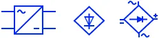
Also known as a full-wave rectifier . It consists of four diodes that convert an AC signal into a DC signal. The process of converting AC to DC is known as rectification.
Controlled bridge rectifier
This type of bridge rectifier is made up of SCRs (thyristors). The switching time of the thyristors can be controlled via its input gate. Thus, the output of this rectifier can be varied by controlling its input gate.
Three-phase rectifier
A three-phase rectifier converts a three-phase electrical signal into rectified direct current. It is a modified form of the full-wave bridge rectifier, in which two pairs of diodes convert each phase.

Comments