
Lecture
High and low temperatures are relative concepts. As far as electronics is concerned, traditional silicon-based devices are usually limited to temperatures below 125°C for reliable operation. In this context, high-temperature electronics can be regarded as electronic devices and packaging in which operating temperatures exceed this standard threshold. Today the term "high temperature" often refers to requirements in the 200-400°C range.
See the table below for a comparative overview of semiconductor technology temperature tolerances.
| Material | Technology maturity | Temperature tolerance (°C) |
|---|---|---|
| Silicon (Si) | Very high | 125-250 |
| Silicon-on-insulator (SOI) | Medium | 250-300 |
| Gallium arsenide (GaAs) | High | 350 |
| Gallium nitride (GaN) | Very low | > 500 |
| Silicon carbide (SiC) | Low | > 750 |
| Diamond | Very low | > 800 |
The aerospace, automotive, and petrochemical industries are increasingly interested in monitoring system operation under harsh conditions. In aerospace, world leaders are striving to create more electric aircraft (MEA). By replacing conventional hydraulic systems with electric actuators and integrating electrical systems into aircraft engines, significant weight savings and improved reliability can be achieved.
In the automotive industry and electric vehicle manufacturing, the need to support an ever-growing number of electrical loads combined with drive systems to boost performance and efficiency will lead to increased use of power electronics.
The petrochemical industry requires sensors capable of assessing the environment around drilling equipment, where the temperature can reach almost 300°C. High-temperature electronics make it possible to improve the reliability of downhole data acquisition devices and enable the installation of permanent sensors during well completion.
Forecasts of high temperatures for the future are given in the table below.
| Application | Projected temperature (°C) |
|---|---|
| Aerospace Distributed engine networks Electromechanical control actuators |
<350 300-600 |
| Under-hood automotive cabin (transmission control unit) On-engine (engine control unit) Wheel mount |
<85 <200 <175 <300 |
| Petrochemical well logging |
|
High-temperature electronics (operating above +150°C) began to be used in oil and gas well drilling many years ago (Fig. 1). To this day, this remains the largest application area for such electronics.
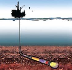
Fig. 1. Well drilling
In the past, drilling was carried out at temperatures no higher than +150…175°C, but the depletion of easily accessible natural resources, combined with technological progress, has prompted industry players to move toward drilling deeper wells, including in regions with an elevated geothermal gradient. The temperature in such wells can exceed +200°C, and the pressure can exceed 170 MPa. Active cooling is practically unfeasible under such unfavorable operating conditions, and passive cooling methods are ineffective when the heated zone is not confined to the electronics itself.
The high-temperature electronics used in drilling can be quite complex. First, during drilling, electronics use sensor signals to steer the drilling equipment along the required trajectory and monitor its operability. When directional drilling technology is used, high-performance geo-navigation equipment guides the wellbore toward a precisely specified geological target.
During drilling, or shortly after its completion, sophisticated downhole instruments collect data about the surrounding geological formations. In this process, known as logging, resistivity, radioactivity, acoustic wave travel time, magnetic resonance, and other parameters are measured to determine formation properties — lithological composition, porosity, permeability, and water/oil-gas saturation. From this data, geologists can draw conclusions about the types of rock in the formation, the types and locations of fluids present in it, and the actual feasibility of extracting sufficient quantities of oil and gas from fluid-saturated zones.
Finally, at the completion and production stages, electronic systems are used to monitor pressure, temperature, vibration, and multiphase flow, as well as to actively control valves. Performing all these functions requires a complete signal chain of components with high performance characteristics (Fig. 2). System reliability is critically important here, since the cost of equipment downtime can be very high. Retrieving and replacing an electronic module in the drill string that has failed several kilometers underground can take more than a day, and the operating cost of a sophisticated deepwater offshore drilling rig is on the order of $1 million per day.
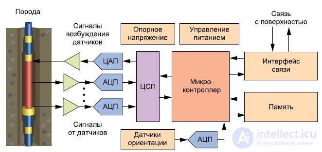
Fig. 2. Simplified diagram of the signal chain of logging equipment
Besides the oil and gas industry, high-temperature electronics are also finding application in other fields, such as avionics. In the aviation industry, there is now a growing trend toward increasing the level of aircraft electrification (more electric aircraft, MEA). Among other things, this initiative is aimed at introducing distributed control systems in place of traditional centralized engine control units. Centralized control requires the use of large, heavy cable systems with hundreds of conductors and numerous connectors of various types. With a shift to a distributed architecture, the control electronics will be located closer to the engine (Fig. 3), which will reduce the complexity of connections by an order of magnitude, lighten the aircraft by hundreds of kilograms, and improve system reliability (which is evaluated, among other things, as a function of the number of connector contacts according to the MIL-HDBK-217F standard).
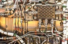
Fig. 3. Electronic control units mounted on an aircraft engine
The drawback, however, is that the ambient air temperature in the immediate vicinity of the engine can range from -55 to +200°C. Although the electronics can be cooled under these conditions, this is undesirable for two reasons: first, the cooling system increases the aircraft's mass and cost, and second, more importantly, a cooling system failure could lead to failure of the electronic units controlling flight-safety-critical systems.
Another component of the initiative to increase aircraft electrification is to replace hydraulic systems with power electronics and electronic control units to improve reliability and reduce maintenance costs. Ideally, the control electronics should be located very close to the actuators, where, again, the ambient temperature is elevated.
Another emerging application for high-temperature electronics is in the automotive industry. As in aviation, there is a shift here from purely mechanical and hydraulic systems to electromechanical or mechatronic systems. This requires moving sensors, signal conditioning circuits, and control electronics closer to heat sources.
The maximum temperature and duration of exposure depend on the type of vehicle and the location of the electronics (Fig. 4). Closer integration of electrical and mechanical systems (for example, combining a gearbox with its control unit) can simplify the manufacturing, testing, and maintenance of automotive subsystems. Functional units of electric and hybrid vehicles associated with high temperatures, such as converters, engine control units, and charging circuits, require power electronics with high power density.
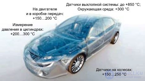
Fig. 4. Typical maximum temperature values in a vehicle
High-temperature electronics can also be used in military and space technology.
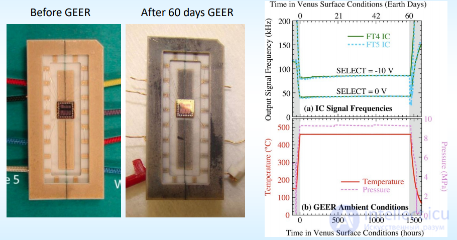
For example, NASA has a so-called Glenn Extreme Environment Rig (GEER), which simulates the surface conditions of Venus. Such equipment is tested there.
60-day Venus Environment IC test (in GEER) 1,2
Two IC versions of a 10 ÷ 2 / ÷ 4 clock signal divider (175 field-effect transistors per chip) operated successfully in
GEER Venus surface conditions for 60 days.
NASA has therefore set itself the goal of achieving and developing, in the near future:
• Development, testing, and modeling of diamond PIN diodes and bipolar junction transistors (BJTs) for actuator drive and low-noise sensor amplification, operating at temperatures > 500°C.
• Growth of diamond epitaxial structures that eliminate defect structures that degrade device performance.
• Development of strategies for low-resistance contacts and stable surface passivation.
• Modeling of device operation, stability, and degradation for high-temperature operation.
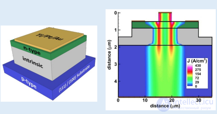
Diagram of a diamond PIN diode structure and simulation of current density in a diamond BJT operating at 500°C
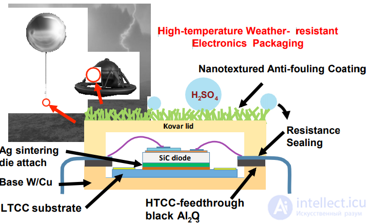
High-temperature weatherproof design for electronics
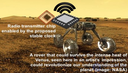
Schematic depiction of a proposed rover on the hot surface of Venus exchanging collected scientific
data with a reliable radio transmitter chip.
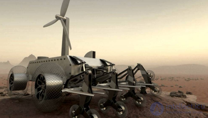
A wind-powered "Venus rover," winner of NASA's open competition "Exploring Hell" 2020
In the past, designers of high-temperature electronics (for example, for the oil and gas industry) were forced to use standard components far beyond their rated temperature range, due to the unavailability of high-temperature ICs. Some standard ICs did work at elevated temperatures, but using them this way was difficult and risky. For example, engineers had to identify potentially suitable components, fully test them, characterize them across the entire temperature range, and evaluate the component's long-term reliability. Under these conditions, the performance and service life of parts are often significantly degraded. This is a difficult, costly, and lengthy process:
Fortunately, thanks to recent advances in integrated circuit manufacturing technology, devices have appeared that can reliably operate at elevated temperatures while guaranteeing compliance with rated specifications. Progress has touched on manufacturing processes, circuit design, and layout methods.
To achieve high-quality device operation at elevated temperature, a whole range of key parameters must be controlled. One of the most important and widely known problems in this regard is the increase in substrate leakage current. Other issues include reduced charge carrier mobility, variation in device parameters (in particular, VT, β, and VSAT), increased electromigration intensity in metal interconnects, and reduced dielectric strength. Although semiconductor dies manufactured using standard processes can remain operational far beyond the upper limit of the military temperature range (125°C), the leakage current in such dies doubles for every 10°C rise in temperature, which is unacceptable in many types of precision equipment.
Technologies such as trench isolation, silicon-on-insulator (SOI), and other modifications of the standard manufacturing process significantly reduce leakage current and make it possible to maintain high performance characteristics at temperatures well above +200°C. Fig. 5 shows how the SOI bipolar process reduces the leakage area. Wide-bandgap materials, in particular silicon carbide (SiC), allow the bar to be raised even further: in laboratory studies, silicon carbide ICs have operated at temperatures up to +600°C. However, silicon carbide technology is still poorly developed and is currently represented on the market only by the simplest components, such as power switches.
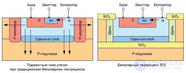
Fig. 5. Comparison of junction leakage mechanisms in bulk silicon and an SOI structure
Instrumentation amplifiers are used in well drilling to amplify very weak signals under the strong noise conditions typically present there. These components are required to have high precision. An amplifier of this type is usually the first stage in the input measurement unit, so its characteristics have a decisive influence on the entire signal chain.
Analog Devices' design team originally intended the AD8229 instrumentation amplifier for operation at high temperatures and designed it with this in mind. To meet the special requirements placed on the device's characteristics, a proprietary bipolar SOI process was chosen for it. The use of special circuit design methods made it possible to guarantee the amplifier's operation across a wide range of parameter values, such as base-emitter voltage and current gain.
IC layout also has a critical influence on the AD8229 amplifier's characteristics and reliability. To maintain low offset voltage and a high common-mode rejection ratio across the entire temperature range, the amplifier's layout was designed to compensate for variation in interconnect parameters and temperature coefficients. Careful analysis of current density in critical areas made it possible to mitigate the effects of electromigration, which became a factor in improving reliability under extreme conditions. Finally, the designers took measures to guard against failure conditions in order to prevent premature breakdown.
Combining a heat-resistant manufacturing process with special circuit design and layout methods made it possible to create an amplifier that meets the strictest accuracy and reliability requirements across the operating temperature range.

Comments