
Lecture
A low-frequency diode usually refers to an AC diode or a diode operating at low frequencies. In general, a diode is a semiconductor device that allows current to flow in only one direction, thanks to the presence of a p-n junction (the boundary between positive and negative regions) in its structure. Such diodes are often rectifying and low-frequency in nature and are used to convert alternating voltage into direct voltage.
These may include, for example, low-frequency rectifiers, detectors, modulators, and other devices designed to work with low signal frequencies.
It is worth noting that the term "low-frequency" is relative and can vary depending on the context of application. For instance, in electronics, low frequencies may be hundreds of kilohertz or even less, whereas in radio communications signals may be considered low-frequency at several megahertz.
Main characteristics of a diode:
Forward Voltage (Vf): This is the voltage that must be applied to the diode in the forward direction (from anode to cathode) for the diode to begin conducting current.
Reverse Voltage (Vr): This is the maximum reverse voltage that can be applied to the diode without destroying it.
High-frequency diode — a semiconductor diode with a p-n junction that has low intrinsic structural and barrier capacitance and a short reverse recovery time.
It is used in mixer circuits and for rectifying (detecting) high-frequency signals. High-frequency diodes are conventionally considered to be those designed for operation at frequencies up to 600 MHz; ultra-high-frequency (microwave) diodes operate up to several tens of GHz.
When manufacturing high-frequency diodes, measures are taken to reduce capacitance and reverse recovery time, for which the junction area is reduced — for example, this is achieved in point-contact diodes — and silicon is doped with gold, so such diodes have relatively low maximum permissible forward current and reverse voltage ratings — up to tens of milliamps and tens of volts.
The main parameters relevant to the application of high-frequency diodes are their capacitance and the limiting frequency at which the diode retains its rectifying properties. Specifications for such diodes also often list the reverse recovery time at a given forward current, or the recovery charge — the charge of minority carriers accumulated in the diode's base while forward current flows.
A high-frequency diode is a diode designed to convert alternating (bipolar) current into direct (unipolar) current of high frequency. The frequency of the current passed by a high-frequency diode is much higher than that passed by a rectifier diode.
High-frequency diodes are made of germanium or silicon, and the p–n junction has a point-contact design. Such a p–n junction design is characterized by a small barrier capacitance (no more than 1 pF). This allows the diode to be used for passing high-frequency currents. However, the small contact area of the p–n junction does not allow significant power to be dissipated. Therefore, high-frequency diodes are less powerful than rectifier diodes and are used in circuits with voltages no higher than several tens of volts and currents on the order of tens of milliamps.
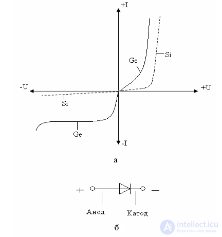
Figure 1.10 – Current-voltage characteristic of a diode (a), graphic symbol (b), and forward-bias polarity
The current-voltage characteristic of a high-frequency diode generally repeats that of a rectifier diode (Figure 1.10, a). The graphic symbol of a high-frequency diode is shown in Figure 1.10, b. The effect of temperature on the reverse current is weaker than in planar diodes — the reverse current doubles with a temperature increase of 15–20°C. Below are the main electrical parameters of high-frequency diodes and their approximate values:
High-frequency diodes are widely used in detectors of amplitude- and frequency-modulated signals, and in various devices for converting high-frequency signals.
Microwave diode — a semiconductor diode designed to operate in the microwave range.
There are several classes of microwave diodes:
Microwave diodes are divided into:
Depending on the internal structure of the diode and the physical effects used in it, microwave diodes of various types are divided into a large number of subtypes. Often diodes of the same subtype can be used in functional units for different purposes. For example, in some cases multiplier microwave diodes may be used in mixers, and so on. The most well-known and widespread types of microwave diodes are:
A diode with a p-i-n structure contains an active base i-region (from the English intrinsic) between two heavily doped, highly conductive n+ and p+ regions. This i-region has low conductivity (close to the intrinsic conductivity of the semiconductor material) and a long carrier lifetime, i.e., it forms a p-i-n junction. This makes it possible to reduce the junction capacitance and increase the operating frequency of the element. The conductivity of the diode depends on the wavelength, intensity, and modulation frequency of the incident radiation. The depletion layer exists throughout almost the entire intrinsic-conductivity region, which has a constant width even under reverse bias. The intrinsic-conductivity region can be expanded by increasing the electron-hole recombination zone. This is what underlies the use of p-i-n diodes in photodetectors.
Switching microwave diodes are designed for use in microwave signal switching devices (in protective devices, in "transmit/receive" switching devices, in scanning antenna arrays, etc.). The operation of such diodes is based on the change of their total impedance at the signal frequency depending on the magnitude and polarity of the bias voltage. Switching diodes come in two types — resonant and p‑i‑n structure diodes (see p-i-n structure diodes).
In resonant diodes, use is made of the possibility of obtaining series or parallel resonance of a circuit composed of the diode's reactances. Circuit parameters are chosen so that under forward bias a parallel-circuit resonance arises, characterized by high resistance. Under reverse bias, series-circuit resonance occurs and the diode resistance drops sharply. Such diodes can switch microwave signals with power up to 1 kW in pulsed mode and up to 10 W in continuous mode, with a switching time of no more than 20 ns.
To increase the level of switched power, the junction area must be increased, which leads to an increase in its capacitance. An increase in junction area with only a slight increase in capacitance is achieved in p-i-n diodes. The basis of any p-i-n diode is a multilayer semiconductor structure, the simplest form of which is shown in Fig. 2.8-4.
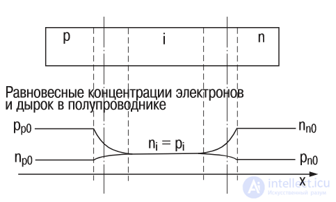
Fig. 2.8-4. Structure of a p-i-n diode
The high-resistance internal i-region typically has a thickness ranging from units to hundreds of microns, with a carrier concentration of about 1013 cm‑3. If the positive terminal of an external DC voltage source is connected to the p-layer and the negative terminal to the n-layer, the concentration of electrons and holes in the i-layer increases due to hole injection from the p-region and electron accumulation from the n-region. In this case, the concentration of injected carriers is 1016...1017 cm-3. A constant forward-direction current flows through the structure. The current density is typically about 10 A/cm2. Under reverse bias, the number of carriers in the i-layer drops relative to the initial value (1013 cm-3) by roughly another order of magnitude. Thus, the number of carriers in the i-layer changes by four orders of magnitude when switching from forward-current mode to reverse-bias mode. The conductivity of the i-layer changes by approximately the same amount.
The DC current-voltage characteristic of a p-i-n diode does not differ qualitatively from that of a p-n diode (Fig. 2.8‑5). The main distinguishing feature of a p-i-n diode is that it represents an inertial nonlinearity. The mechanism by which a microwave voltage acts on the diode differs radically from the effect of a DC voltage or a voltage of relatively low frequency.
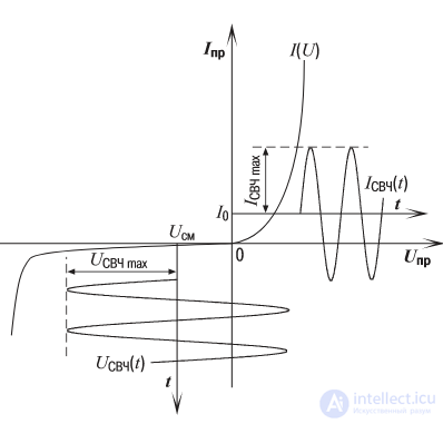
Fig. 2.8-5. Static current-voltage characteristic of a p-i-n diode and the effect of a microwave signal on it
When a forward DC current acts on the diode, a stored charge appears in the i-layer. When the diode is connected in parallel across a transmission line, a microwave current flows through it. The effect of this current on the stored charge, i.e., on the diode's conductivity, is much weaker than that of DC current. This is because the change in charge occurring during the positive half-cycle of the microwave current is much smaller than the stored charge. During negative half-cycles of the microwave oscillation, when current through the diode should theoretically be absent (Fig. 2.8‑5), the change in stored charge and, correspondingly, in diode conductivity also turns out to be insignificant.
The difference between the effects of DC and microwave currents on diode conductivity increases with increasing carrier lifetime and increasing microwave oscillation frequency. At zero or negative bias, the diode's low conductivity, due to its inertia, is maintained even at relatively high microwave voltages. Short positive voltage pulses lasting less than half the period of the microwave oscillation (Fig. 2.8‑5) are insufficient to change the diode's conductivity. Thus, for microwave oscillations, both in forward-current mode and reverse-bias mode, a p‑i‑n diode can, to a first approximation, be regarded as a stationary linear two-terminal device.
The power of the signal switched by p‑i‑n diodes can reach hundreds of kilowatts in a pulse. However, the switching time of these diodes is longer than that of resonant switching diodes, since their operation is based on the inertial processes of carrier injection and recombination/depletion. With a significant increase in microwave current or a decrease in oscillation frequency, p-i-n diodes may exhibit a change in diode conductivity under the influence of microwave signals, as well as detection effects. These phenomena, on the one hand, reduce the value of the switched power, but on the other hand, are useful in constructing semiconductor microwave limiters.
The main parameters of switching diodes include: isolation loss (Liso) and insertion loss (Lins), the related quality factor (K), and the diode's critical frequency (fcr), forward and reverse recovery time, stored charge, and others.
Isolation loss (Liso) and insertion loss (Lins). Any switching diode is characterized by two main operating modes. The first mode is a state of the diode in which the signal it switches, of the corresponding power and frequency, passes freely through the switched circuit (transmission mode). The second mode consists of the diode blocking the switched circuit at the frequency of the switched signal (isolation mode). Switching is accomplished by changing the diode's resistance at the operating frequency. The isolation mode corresponds to low resistance, while the transmission mode corresponds to high resistance. To describe the main properties of a diode switch in both modes, a quantity is used equal to the ratio of the microwave signal power supplied to the switching device to the power passing through this device. This ratio, usually expressed in decibels, is called isolation loss (Liso) for the isolation mode, and insertion loss (Lins) for the transmission mode. Knowing these losses, one can easily determine the power dissipated in the diode in either operating mode:
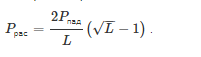
Obviously, in isolation mode the dissipated power is higher and must not exceed the maximum permissible value for the specific diode used in the circuit.
Diode quality factor (K). To provide a generalized characterization of the loss parameters of a switching diode, a special coefficient has been introduced, called the quality factor of a switching diode. This coefficient is calculated using the formula:
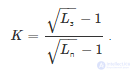
Thus, the diode's quality factor does not depend on the circuit in which it is connected to the line, the line's characteristic impedance, etc., but is entirely determined by the characteristics of the internal p‑i‑n structure and the signal parameters.
Critical frequency (fcr). The effectiveness of diodes used in microwave switching devices can also be assessed using a parameter called the critical frequency (fcr). The critical frequency is the input signal frequency at which (as frequency is gradually increased) the capacitive reactance of the diode structure becomes equal to the geometric mean of its active resistance under forward current and reverse bias.
In general, for the critical frequency the following holds:
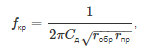
where:
Cd — diode capacitance,
rfwd — forward loss resistance,
rrev — reverse loss resistance.
The critical frequency is directly related to the diode's quality factor, which can be calculated for an operating signal of frequency f using the following formula:
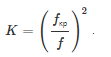
Typically, the parameter set of a switching diode includes: critical frequency, capacitance, and microwave resistance at a given value of forward current. The diode's active resistance under negative bias can be found from the formulas given above.
One of the most significant varieties of diodes is microwave detector diodes.
The main purpose of a detector diode is to recover, from a modulated voltage, the low-frequency signal that was used as the basis for amplitude-modulating the high-frequency signals.
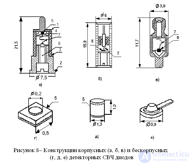
The role of a detector diode is played mainly by a point-contact diode or a Schottky diode. The most important characteristic of this element is considered to be the steepness of the I-V curve near the operating point. The value of the detector's output voltage should be directly related to how powerful the microwave signal is (the square of the input voltage).
The operation of a microwave detector diode generally does not involve shifting of the operating point. However, when detecting a weak signal, it is appropriate to place the operating point in the low-voltage region. This is possible for microwave diodes of the forward-biased type.
A certain number of detector diodes have a characteristic close to quadratic. As a result, they can be used to determine the power of microwave oscillations.
The main special characteristics of detector-type diodes are considered to be:
When a modulated high-frequency signal is applied to a microwave diode, a current begins to flow through the diode in addition to it. If one determines the ratio of the increment in the diode's rectified current to the microwave power that caused this increment, the resulting value is a measure of current sensitivity. This quantity is determined for a given load, once the operating mode has been established.
The voltage sensitivity of a microwave detector diode is calculated in a similar way. The only difference is that the voltage increment is used instead of the current increment. This characteristic is often determined only for diodes used in detecting pulsed-type signals. It should be remembered that sensitivity tends to decrease as temperature increases.
There is another important parameter for detector diodes — tangential sensitivity. The main purpose of this criterion is to determine the lowest boundary of the signal that can be detected.
The quality factor of a detector diode makes it possible to immediately assess all of its basic parameters in terms of efficiency. However, this value is calculated using a fairly complex formula.
A diode can be represented as a lumped-parameter system if its linear dimensions (housing length, junction thickness) are small
compared to the wavelength.
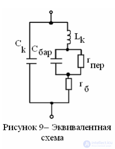
The equivalent circuit of a microwave detector diode is shown in Figure 9. Here the junction is represented by differential parameters — the junction resistance
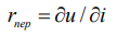 and the barrier capacitance CBAR.
Losses in the diode base, ohmic junctions, and leads are represented by a series loss resistance
rb, the inductance of the leads and contact spring is LK, and the structural
capacitance between the leads in the absence of contact with the diode structure is CK.
Due to the voltage drop across rb and LK, the voltage applied to the junction turns out to be lower than that applied to the diode, and the capacitance CK shunts it. These parameters are called parasitic. Typical values of LK are tenths of a nanohenry
and CK — tenths of a picofarad, rb — tenths of an ohm or a few ohms. In chip (unpackaged) diodes, the values of CK and LK are roughly an order of magnitude smaller, which is why
their efficiency is higher. The value of the differential resistance rj can
vary over a wide range depending on the position of the operating point on the diode's I-V curve,
while the value of CBAR is tenths of a picofarad.
The circuit parameters can be determined by measurements at low frequencies
or approximately based on the rectification process. The equivalent circuit is used to calculate the characteristics of the detector diode at high frequencies.
Turning to the simplified equivalent circuit (Figure 10, a), let us consider the various operating modes of the diode.
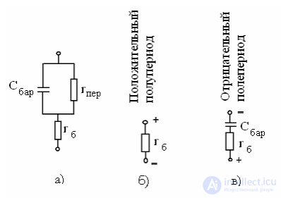
a – simplified equivalent circuit; b – forward resistance; c – reverse resistance
Figure 10 – Diode operating mode
During the positive half-cycle  , and the junction capacitance is negligible,
therefore the forward resistance Rfwd=rb (Figure 10, b) ( 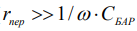 ⋅ ).
⋅ ).
During the negative half-cycle, the junction resistance rj is large, therefore 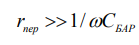 and its influence can be neglected.
Consequently, the reverse resistance 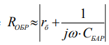 (Figure 10, c).
Limiting ourselves to the range of frequencies at which 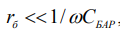 , we obtain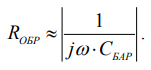
The rectifying properties of a diode are evaluated using the rectification coefficient:

By U one may understand the amplitude value of the high-frequency oscillation voltage applied to the diode in the mode when there is no load resistance.
Thus
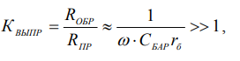
from which the condition for effective diode operation is that the following inequality holds
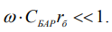
Therefore, in microwave diodes, an effort is made to reduce the capacitance CBAR by using
a point-contact junction for this purpose. To reduce rb, a low-resistivity semiconductor material is used.
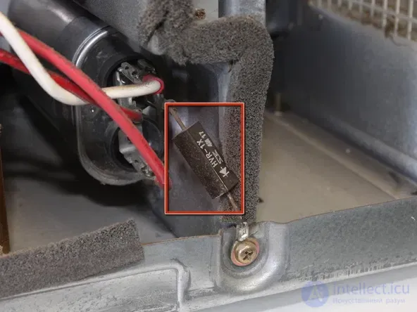
One of the most common problems is the failure of the high-voltage microwave diode in a microwave oven.
In terms of design, a microwave oven diode is a large number of diodes connected in series, ultimately forming a single unit. This element contains rectifier diodes as its components. Technologically, they are manufactured in exactly the same way, and moreover, are enclosed in a common housing. The assembly of a high-voltage diode does not involve the use of capacitors or resistors that could equalize the voltage.
As a result: this type of diode has a nonlinear current-voltage characteristic. Therefore, the resistance data for high-voltage diodes directly depends on the magnitude of the voltage applied.
This type of assembly makes it quite difficult to analyze the functionality of a microwave diode.
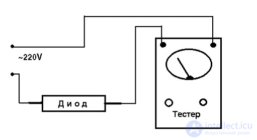
Important to remember! Testing a microwave diode with a simple tester is not possible. It will not give accurate readings, and the tester will not show forward and reverse resistance data.
It is much better to use a multimeter. In doing so, resistance readings must be taken for both the forward and reverse directions.
Before connecting the multimeter, its mode must be set to R x 1000. As a result, when the "+" probe of the instrument is connected to the anode of the microwave diode, the resistance will be measured in the forward direction. The value shown on the display will be finite in this case. When the connection is made through the cathode ("-" probe), the value will be infinite.
To assess the serviceability of a diode in a microwave oven, the following steps must first be carried out:
For the incandescent lamp in this circuit, a low power rating is preferable — around 15 V when connected to 220 V. It is important that the lamp glow at about half its possible brightness and clearly flicker.
If, when the microwave diode is connected in the forward and reverse directions, this is indeed what happens, then everything is fine. If, however, the nature of the glow changes after flipping the diode, this indicates the presence of a "breakdown" and the need to replace the diode element.
Another method for testing microwave diodes requires the use of a charger from a mobile phone or tablet, which typically has a voltage of 5 V. In addition, a multimeter (analog "tseshka") is needed.
Once everything necessary has been prepared, you can proceed with the check:
If the diode is functional, the meter's needle will settle at a reading of 0.25 V (for the forward direction), or will show no reading at all (for the reverse direction).
If there are faults or "breakdowns," there will be no reading in either direction.
If faults are found in the operation of the microwave diode, it must be replaced.

Comments