
Lecture

Rectifier (of electric current) — a converter of electrical energy; a mechanical, electron-tube, semiconductor, or other device designed to convert an input alternating electric current into a direct current (that is, a unidirectional current), or in the particular case, into a constant output electric current.
Most rectifiers produce not a constant but a pulsating current; filters are used to smooth out the ripple.
A device that performs the reverse function — converting direct current into alternating current — is called an inverter.
Due to the reversibility principle of electric machines, a rectifier and an inverter are two varieties of the same electric machine (this is true only for an inverter based on an electric machine).
Rectifiers are classified according to the following criteria:
Can be built using a bridge or half-bridge circuit (in which, for example, when rectifying single-phase current, a special transformer is used with a tap from the midpoint of the secondary winding and half as many current-rectifying elements; this circuit is now rarely used, since it requires more metal and has a higher equivalent internal resistance, i.e., greater heating losses in the transformer windings).
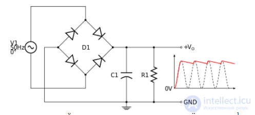
When building a full-wave rectifier with a smoothing capacitor, one should always remember that alternating voltage is always measured in "RMS" (root-mean-square) value, which is 1.41 times smaller than its maximum amplitude, while the rectified voltage across the capacitor, in the absence of a load, will always equal the peak value. This means that, for example, with a measured single-phase AC voltage of 12 volts ahead of a single-phase bridge rectifier with a smoothing capacitor, the voltage on the capacitor (with no load) will be up to 17 volts. Under load, the rectified voltage will be lower (but not lower than the average rectified value of the AC voltage, assuming the internal resistance of the transformer — the AC source — is taken to be zero) and will depend on the capacitance of the smoothing capacitor.
Accordingly, the choice of the AC voltage of the transformer's secondary winding should be based on the maximum permissible value of the supplied voltage, and the capacitance of the smoothing capacitor should be large enough that the voltage under load does not drop below the minimum permissible value. In practice, the inevitable voltage drop under load — across the resistance of the wires, the transformer winding, the diodes of the rectifier bridge — as well as a possible deviation of the mains supply voltage from its nominal value, must also be taken into account.
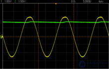
It should be noted that in rectifiers with a smoothing capacitor, the diodes do not open for the entire half-cycle of the voltage, but only for short intervals of time, when the instantaneous value of the alternating voltage  exceeds the constant voltage across the filtering capacitor (i.e., at moments near the peaks of the sine wave). Therefore, the current flowing through the diodes (and the transformer winding) consists of short, powerful pulses of complex shape, whose amplitude significantly exceeds the average current drawn by the rectifier's load. This fact must be taken into account when designing the transformer (the calculation variant for operation not into a resistive load, but into a rectifier with a capacitive filter), and measures must be taken to suppress the resulting impulse noise.
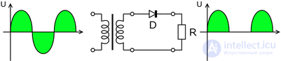
The simplest half-wave rectifier circuit consists of only a single current-rectifying element (a diode). The output is a pulsating direct current. At industrial frequencies (50–60 Hz), it is not widely used, since powering equipment requires smoothing filters with large capacitance and inductance values, which increases the size and weight of the rectifier. However, the half-wave rectification circuit has become very widely used in switching power supplies with an AC frequency above 10 kHz, which are widely used in modern household and industrial equipment. This is because at higher rectified-voltage ripple frequencies, achieving the required characteristics (a specified or permissible ripple factor) requires smoothing elements with smaller capacitance (inductance) values. The weight and size of power supplies decrease as the frequency of the input AC voltage increases.
The half-wave rectifier, or quarter-bridge, is the simplest rectifier and includes a single valve (diode or thyristor).
Assumptions: the load is purely resistive, and the valve is an ideal electrical switch.
The voltage from the transformer's secondary winding passes through the valve to the load only during the positive half-cycles of the AC voltage. During the negative half-cycles, the valve is closed, the entire voltage drop occurs across the valve, and the voltage on the load Uн (Uload) is zero. The average value of the alternating voltage relative to the applied RMS value will be:
 . This value is half of that in a full-bridge rectifier. It is important to note that the RMS (formerly "effective") value of the voltage at the output of a half-wave rectifier will be smaller than the applied RMS value by a factor of
  , and the power consumed by the load is 2 times smaller (for a sinusoidal signal shape).
Disadvantages :
Advantages:
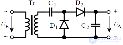
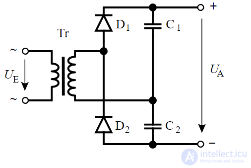
Using two diodes and two capacitors, widely known as the "voltage doubler" or "Latour–Delon–Greinacher doubler."
There is also a known current-doubling circuit: two series-connected chokes are connected in parallel to the single secondary winding of the transformer, and the midpoint of the connection between them is used as the midpoint in a "full-wave rectifier with a center tap." [11]

Using four diodes, widely known as "full-wave," invented by the German physicist Leo Graetz. The area under the integral curve equals:
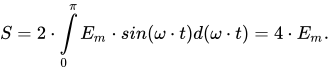
The average EMF equals  , i.e., twice as much as in the quarter-bridge circuit.
The equivalent internal resistance equals  .
.
The ripple frequency equals  , where
  is the mains frequency.
The highest instantaneous voltage on the diodes is 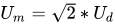
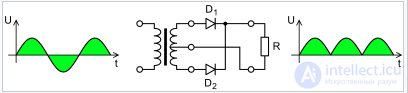
Widely known as "full-wave with center tap." Proposed in 1901 by Professor V. F. Mitkevich. In this rectifier, two windings in phase opposition create a two-phase alternating current with a 180-degree phase shift between them. The two-phase alternating current is rectified by two half-wave quarter-bridge rectifiers connected in parallel and working into a common load. During one half-cycle, current flows to the load from one half of the secondary winding through one valve; during the other half-cycle, from the other half of the winding, through another valve. It was used when copper was cheaper than diodes. The drawback of the circuit is a more complex and less efficient (in terms of copper and steel) transformer design[12]. In modern conditions, its use is justified when the amplitude of the rectified voltage is comparable to the forward voltage drop across a solid-state diode junction (i.e., rectifiers for voltages of only a few volts), since under these conditions it has significantly better efficiency compared to the bridge circuit.
The area under the integral curve equals:
The average EMF equals: 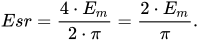
The relative equivalent internal resistance equals  , i.e., twice as much as in a single-phase full-bridge circuit, and hence greater energy losses due to heating of the transformer winding copper (or greater copper consumption).
The load current equals
The load power equals
The ripple frequency equals , where is the mains frequency.
Allows the use of diodes with an average current almost half that required in a single-phase full-bridge circuit.
Based on two parallel full bridges.
The area under the integral curve equals:

The average EMF equals:  , i.e., times greater than in a single-phase full-bridge circuit.
In the no-load mode and modes close to it, the EMF in the bridge with the largest EMF over a given segment of the period reverse-biases (closes) the diodes of the bridge with the smaller EMF over that same segment. The equivalent internal resistance in this case equals  . As the load increases (as
  decreases), segments of the period appear and grow in which both bridges operate in parallel into the common load; the equivalent internal resistance over these segments of the period equals
  . In the short-circuit mode, both bridges operate in parallel into the load throughout the entire period, but the useful power in this mode is zero.
Based on two series-connected full bridges.
The area under the integral curve equals:

The average EMF equals: 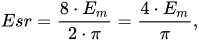 , i.e., twice as much as in a single-phase full-bridge circuit.
The relative equivalent internal resistance equals 
Sometimes, in radio-receiving equipment or in audio-frequency stages of power supplies, so-called shunting capacitors are used across each diode of a full-wave rectifier
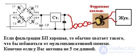
It is possible to power a device this way, but multiplicative interference may appear. In the receiver, AC hum will be audible, but this hum does not arise from poor power supply, but for another reason. This is multiplicative interference passing through the power supply.
The first thing needed is to shunt each diode in the bridge with a capacitor of about 1000 pF
Depending on the nature of their effect on the signal, interference is distinguished as additive or multiplicative (non-additive). Additive interference manifests itself independently of the signal. The effects of the signal and additive interference add together. Multiplicative interference occurs only in the presence of a signal. Its effect manifests itself as an irregular change in the signal level. With multiplicative interference, unlike additive interference, increasing the amplitude of the received signal does not improve the quality of its reproduction. An example of additive interference is a radio receiver's own noise; an example of multiplicative interference is a fading effect.
Capacitors are usually placed in parallel with the bridge diodes to reduce noise caused by the switching of the diodes themselves at low load currents, when the diodes open only at the very peak of the half-cycle and charge the filter capacitance with short pulses of high current.
In radio-transmitting equipment, where high-voltage assemblies of rectifier diodes are often used, for example as shown in the figure

Each diode is shunted by a resistor to evenly distribute the reverse voltage. Shunting capacitors of 0.01 μF are needed to eliminate the so-called "white noise" that may accompany operation on transmission.
Many people believe that the purpose of a capacitor in parallel with a pn junction is to eliminate sharp voltage fluctuations, which, due to the inertia of the junction, cause currents that needlessly heat the crystal and/or may damage it. For similar reasons, a small-capacitance choke (a ferrite bead or tube on the diode lead) is placed in series with the diode. But the cause of impulse voltages at the junction can be either interference from the mains or steep voltage fronts arriving from the secondary winding of PWM circuits. In old linear mains power supply circuits for radio-electronic equipment, it was typical to place 10–20 nF capacitors in parallel with the bridge diodes.
1. Shunting a diode with a resistor — in parallel. Purpose: to prevent excessive reverse current in the case of several diodes connected in series.
When rectifying high voltages, diodes must be connected in series so that the reverse voltage across each diode does not exceed the limiting value. However, due to variation in the reverse resistances of different diode samples of the same type, the reverse voltage on individual diodes may turn out to be higher than the limit, which would lead to diode breakdown.
In order for the reverse voltage to be distributed evenly among the diodes, regardless of their reverse resistances, shunting with resistors is used. The resistances Rsh of the resistors must be equal and significantly less than the smallest of the diodes' reverse resistances. At the same time, however, Rsh must not be too small, so that the current at reverse voltage does not increase excessively, i.e., so that rectification is not degraded.
Parallel connection of diodes is used when a forward current greater than the limiting current of a single diode is needed. But if diodes of the same type are simply connected in parallel, then due to differences in their volt-ampere characteristics they will be unevenly loaded, and in some of them the current will exceed the limit.
Equalizing resistors Req are selected experimentally until equal currents are obtained in the diodes under operating conditions.
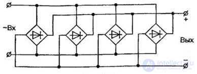
Figure 2. Diagram of the parallel connection of diode bridges, for the high currents of a welding machine.
Thus, while series connection is quite justified for increasing the maximum reverse voltage, parallel connection of diodes is not an effective way to increase the forward current, given the availability of cheap, powerful diodes.
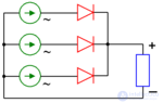
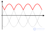
The most common three-phase rectifiers are the V. F. Mitkevich circuit (using three diodes, proposed by him in 1901) and the A. N. Larionov circuit (using six diodes, proposed in 1923). The Mitkevich rectifier is a parallel quarter-bridge type, while the Larionov rectifier is a parallel half-bridge type
|
|
("Partially three-phase, half-wave, with center tap"). The area under the integral curve equals:

The average EMF equals: 
In no-load and near-no-load modes, the EMF in the branch with the largest EMF over a given segment of the period reverse-biases (closes) the diodes in the branches with a smaller EMF over that segment, and the relative equivalent resistance equals the resistance of a single branch  . As the load increases (as decreases), segments of the period appear and grow in which both branches operate on a single load in parallel, and the relative equivalent resistance over these segments equals
  . In the short-circuit mode, these segments are maximal, but the useful power in this mode is zero.
The ripple frequency equals  , where is the mains frequency.
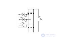
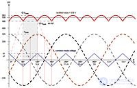
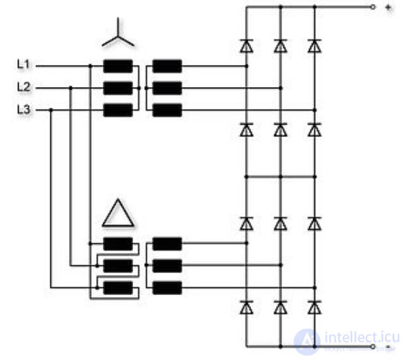
In some electrical engineering literature, the "delta-Larionov" and "star-Larionov" circuits are sometimes not distinguished, although they have different values of average rectified voltage, maximum current, equivalent internal resistance, etc.
In the "delta-Larionov" rectifier, ohmic losses in the copper transformer winding are greater than in the "star-Larionov" rectifier, which is why the "star-Larionov" circuit is more often used in practice.
In addition, A. N. Larionov's rectifiers are often called bridge rectifiers, but in fact they are parallel half-bridge circuits.
In some literature, Larionov-type rectifiers and similar ones are called "full-wave," but in fact the rectifiers that are truly full-wave are the "three series bridges" circuit and similar ones.
The area under the integral curve equals: 
The average EMF equals:  , i.e., greater than in the Mitkevich rectifier.
The operation of the "delta-Larionov" circuit involves two periods. The large period equals 360° ( ). The small period equals 60° (
 ), and repeats 6 times within the large period. The small period consists of two small half-periods of 30° (
 ), which are mirror-symmetric, so it is sufficient to analyze the circuit's operation over one small half-period of 30°.
In no-load and near-no-load modes, the EMF in the branch with the largest EMF over a given segment of the period applies a negative voltage (relative to the cathode) to the anode of the diodes, which closes them relative to the branches with smaller EMF over that segment.
At the initial moment ( ), the EMF in one of the branches equals zero, while the EMF in the other two branches equal
  , and in this state two upper diodes and one lower diode are open. The equivalent circuit represents two parallel branches with equal EMFs (0.86) and equal resistances of
  each; the equivalent resistance of both branches equals
  . Further, during the small half-period, one of the two EMFs equal to 0.86 rises to 1.0, another decreases to 0.5, and a third rises from 0.0 to 0.5. One of the two open upper diodes closes, and the equivalent circuit becomes a parallel connection of two branches, in one of which there is the larger EMF with resistance equal to , while in the other branch a series connection of the two smaller EMFs is formed, with resistance equal to
  ; the equivalent resistance of both branches equals

The ripple frequency equals  , where is the mains frequency. The absolute ripple amplitude equals:

The relative ripple amplitude equals  .
.
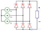
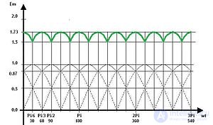
The star-Larionov rectifier (six-pulse) is used in the onboard power-supply generators of almost all types of vehicles (road, water, submarine, air, etc.). In the electric drives of diesel locomotives and diesel-electric ships, almost all the power passes through a star-Larionov rectifier.
The area under the integral curve equals:
 .
.
The average EMF equals:  , i.e.,
  times greater than in the "delta-Larionov" and "three parallel full bridges" circuits, and twice as great as in the Mitkevich circuit.
This rectifier has a large period equal to 360° and a small period equal to 60°. The large period contains 6 small periods. The small period of 60° consists of two mirror-symmetric parts of 30° each, so it is sufficient to analyze the operation of this circuit over one 30° portion of the small period.
At the beginning of the small period ( ), the EMF in one of the branches equals zero, while in the other two it equals
  each. These two branches are connected in series. The equivalent internal resistance in this case equals
  . Further, one of the EMFs increases from 0.86 to 1.0, another decreases from 0.86 to 0.5, and a third increases from 0.0 to 0.5.
The equivalent circuit in this case represents two series-connected branches, in one of which there is a single EMF with resistance equal to the resistance of one winding, 3*r, while in the other there are two parallel-connected EMFs with resistance  each; the equivalent resistance of the two parallel branches equals
  . The equivalent internal resistance of the whole circuit equals
 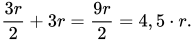 . In modes close to no-load (at light loads), among the parallel branches, the EMF in the branch with the larger EMF reverse-biases (closes) the diode in the branch with the smaller EMF, which changes the equivalent circuit. As the load increases, segments of the period appear and grow in which both branches operate on the load in parallel. In the short-circuit mode, the segments of parallel operation increase to cover the entire period, but the useful power in this mode is zero.
The ripple frequency equals , where is the mains frequency. The absolute ripple amplitude equals  .
.
The relative ripple amplitude equals 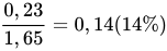 .
.
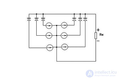
In the literature this is sometimes called "six-phase" (see Gleichrichter für Dreiphasenwechselstrom, fig. Sechspuls-Sternschaltung (M6): 6-Phasen-Gleichrichter mit Mittelpunktanzapfungen am Drehstromtransformator), German.
It is almost an analog of the "three full bridges in parallel" rectifier and has almost the same properties as the "three full bridges in parallel" rectifier, but the equivalent internal resistance is almost twice as large, the number of diodes is half as many, and the average current through a single diode is almost twice as great.
The area under the integral curve equals:
 .
.
The average EMF equals:  , i.e., the same as in the "delta-Larionov" circuit and times smaller than in the "star-Larionov" circuit.
It is almost an analog of the "three full bridges in series" rectifier and has almost the same properties, but the equivalent internal resistance is almost twice as large, the number of diodes is half as many, and the average current through a single diode is almost twice as great.
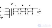
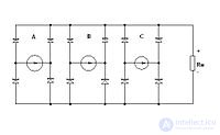
Less well known are full-bridge three-phase rectifiers based on the "three parallel bridges" circuit (using twelve diodes), the "three series bridges" circuit (also using twelve diodes), and others, which surpass the A. N. Larionov rectifier in many parameters.
Looking at the rectifier circuits, one can see that the V. F. Mitkevich rectifier is an "incomplete" version of the A. N. Larionov rectifier, and the A. N. Larionov rectifier is an "incomplete" version of the "three parallel bridges" rectifier.
The area under the curve, i.e. the integrand, equals:
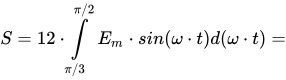
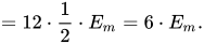
The average EMF equals:

that is, the same as in the "delta-Larionov" circuit and times smaller than in the "star-Larionov" circuit.
In no-load mode, the EMF in the bridge with the largest EMF over a given segment of the large period reverse-biases (closes) the diodes in the bridges with a smaller EMF over that segment of the large period. The equivalent internal resistance in this case equals the resistance of one bridge, . As the load increases (as decreases), segments of the period appear and grow in which two bridges operate on the load in parallel; the equivalent internal resistance over these segments of the period equals the resistance of two parallel bridges,  . With a further increase in load, segments of the period appear and grow in which all three bridges operate on the load in parallel; the equivalent internal resistance over these segments of the period equals the resistance of three parallel bridges, . In the short-circuit mode, all three bridges operate in parallel into the load, but the useful power in this mode is zero.
The "three parallel full bridges" rectifier has the same average EMF at no load as the "delta-Larionov" rectifier, and the same winding resistances, but, since its diodes operate independently of the neighboring phases, the moments of diode switching differ from the moments of diode switching in the "delta-Larionov" circuit. The load characteristics of these two rectifiers turn out to be different.
The ripple frequency equals , where is the mains frequency.
The absolute ripple amplitude equals  .
.
The relative ripple amplitude equals  .
.
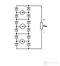
The area under the integral curve equals: 
The average EMF equals:  , i.e., greater than in the "star-Larionov" circuit.
The equivalent internal resistance equals the resistance of three series-connected bridges, each with resistance 3*r, that is,  .
.
The load current equals
The load power equals
The ripple frequency equals , where is the mains frequency.
This rectifier has the highest average EMF and can be used in high-voltage power sources (in industrial gas electrostatic cleaning installations (electrostatic precipitators), etc.).
Like three-phase rectifiers, multiphase rectifiers can be full-bridge, half-bridge, or quarter-bridge, connected in parallel and separate, parallel combined in star, parallel combined in ring, series, or series-parallel configurations.
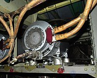
This consists of a parallel (or sometimes series) connection of two Larionov rectifiers with a phase shift of the input three-phase currents. This doubles the number of rectified half-cycles compared to a conventional Larionov rectifier, which reduces the relative amplitude of the rectified voltage ripple and doubles the ripple frequency of the rectified voltage, which also facilitates smoothing of the rectified voltage. In practice, this circuit is quite popular and is used both in powerful rectifiers of traction substations of electric transport, where it is important to supply commutator traction motors with minimal ripple, and in rectifier units of aircraft, where electromagnetic compatibility is important[14][15].
Voltage-multiplying rectifiers are used in cases where, for some reason, the input alternating voltage must be lower than the output direct voltage. For example, in domestic (Soviet/Russian) televisions, starting from certain models of the later ULPTsT series and up to the 4USTsT, a high-voltage multiplier was used in the anode circuit of the picture tube.
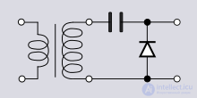
Proposed by Villard in 1901[16]. It consists of a capacitor connected in series with the winding, and a diode connected in parallel with the load. During the negative half-cycle, current flows through the circuit "AC source — capacitor — diode," and the capacitor charges. During the positive half-cycle, the charged capacitor is connected in series with the transformer, and their voltages add together.
A feature of this rectifier is that a choke must necessarily be used as the smoothing filter, since the capacitor will discharge during the negative half-cycle.
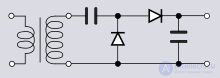
Proposed by Greinacher in 1913 (published in 1914[17]). This rectifier contains 2 diodes. The operating principle is the same as that of the Villard rectifier, but a capacitor can be used as a smoothing filter. Such a circuit is often used as an amplitude detector in radio receivers.
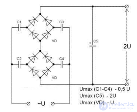
The bridge voltage doubler resembles the Graetz bridge, but unlike it, capacitors are installed instead of diodes in one of the bridge arms. Because of this, during each half-wave either one or the other capacitor is connected to the input circuit, and the output voltage of the rectifier is made up of the voltages on the two capacitors.
The Cockcroft–Walton multiplier allows the output voltage to be increased several times over. It is used in circuits where a very high voltage needs to be obtained.
Voltage multipliers have certain drawbacks compared to ordinary rectifiers:
These features determined the field of application of voltage multipliers — most often in low-power devices that are not demanding on power quality.
Rectifiers are usually used wherever alternating current needs to be converted into direct current. The use of rectifiers to convert alternating current into direct current gave rise to the concept of the mean absolute value of current (that is, without regard to the sign of the ordinate) over a period. In full-wave rectification, the mean absolute value is defined as the arithmetic mean of all the ordinates of both half-waves over a full period without regard to their sign (that is, taking all ordinates over the period as positive, as is the case with ideal full-wave rectification).
Consumers of electric power with nonlinear characteristics are, first and foremost, all kinds of installations that convert alternating current to direct current using various valves.
These include rectifier installations for:
Until fairly recently, mercury-arc rectifiers (both uncontrolled and controlled) were mainly used as valves. Nowadays, silicon semiconductor rectifiers are the predominant choice. Thyristor rectifiers are being introduced.
Rectifier installations are usually built with a large capacity and are connected via special transformers to a supply network at a voltage of 6–10 kV. Low-power rectifier installations are built using a three-phase circuit with a neutral (zero) lead.
The use of rectifiers in the power supplies of radio and electronic equipment is due to the fact that alternating current is typically used in the power supply systems of buildings or vehicles (aircraft, trains), and the output current of any electromagnetic transformer used for galvanic isolation of circuits or for stepping down voltage is always alternating, whereas in most cases the electronic circuits and electric motors of the target equipment are designed to run on direct current.
As a rule, alternating-current generators are used on autonomous vehicles (cars, tractors, diesel locomotives, ships, nuclear-powered vessels, aircraft) to produce electric power, since they have greater power for a smaller size and weight than direct-current generators. However, direct-current motors are usually used to drive the propulsion units of transport, since they allow the direction of motion to be controlled by simply switching the poles of the supply current, and they have the required traction characteristics (high torque at low rotor speed). This makes it possible to dispense with complex, heavy, and unreliable gearboxes. This is also used to drive the drilling rigs of drilling derricks.
Electric power on a vehicle is usually generated by an alternating-current generator, but the onboard equipment requires direct current for its power supply. For example, in passenger cars the direct-current onboard network is powered by a semiconductor rectifier built into the alternator.
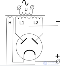
Direct-current welding machines most often use bridge circuits built on powerful silicon rectifying diodes — valves — in order to obtain direct welding current. It differs from alternating current in that, when it is used, the arc region near the positive ( ) pole heats up more strongly, which makes it possible either to carry out gentler welding of the workpieces predominantly with a consumable welding electrode, or to save on electrodes by cutting metal with electric arc welding. In some cases, when special welding electrodes are used, electric arc welding with alternating current is not possible at all.
Factories are supplied with power from an alternating-current network, but for driving rolling mills and other units it is more advantageous to use direct-current motors, for the same reason as for vehicle motors.
As part of rectennas:
The ballistic rectifier, described in the article "Room-Temperature Ballistic Nanodevices" by Aimin M. Song , may find application for detecting very high-frequency signals (up to 50 GHz).
Until about 1905, when tube rectifiers were developed, energy conversion devices had a purely electromechanical design. Mechanical rectifiers used some form of rotation or resonant vibration driven by electromagnets, which actuated a switch or commutator to reverse the direction of current.
These mechanical rectifiers were noisy and required substantial maintenance costs. The moving parts experienced friction, which required lubrication and replacement due to wear. Breaking mechanical contacts under load caused electric arcs and sparks, which heated and corroded the contacts. They also could not operate at alternating-current frequencies above a few thousand cycles per second.
A synchronous rectifier can be used to convert alternating current to direct current in electric locomotives. It consists of a synchronous motor driving a set of heavy-duty electrical contacts. The motor rotates in step with the frequency of the alternating current and periodically swaps the connections to the load at the moment the sinusoidal current passes through zero. These contacts do not need to switch a large current, but they must be able to carry a large current to supply direct current to the traction motors of a diesel locomotive.
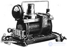
These consisted of a resonant reed, vibrating under the action of an alternating magnetic field produced by an AC electromagnet, with contacts that reversed the direction of the current on the negative half-cycles. They were used in low-power devices such as battery chargers to rectify the low voltage produced by a step-down transformer. Another use was in battery power supplies for portable vacuum-tube radio receivers, to provide the high direct voltage needed for the tubes. They functioned as a mechanical version of modern solid-state switching inverters, with a transformer to step up the battery voltage and a set of vibrator contacts on the transformer core, driven by its magnetic field, to repeatedly interrupt the battery's direct current to create a pulsating alternating current for feeding the transformer. A second set of rectifier contacts on the vibrator would then rectify the high alternating voltage from the transformer's secondary winding into direct current.
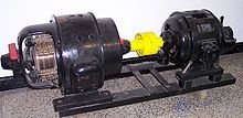
A motor-generator set, or a similar rotary converter, is not strictly a rectifier, since it does not actually rectify a current but instead generates direct current from an alternating-current source. In an "MG set" the shaft of the AC motor is mechanically coupled to the shaft of a DC generator. The DC generator produces multiphase alternating currents in its armature windings, which a commutator on the armature shaft converts into a direct-current output; or a homopolar generator produces direct current without a commutator. MG sets are useful for producing direct current for railway traction motors, industrial motors, and other high-current applications, and were common in many high-power DC sources (for example, in carbon-arc lamp projectors for street cinemas) before high-power semiconductors became widely available.
The electrolytic rectifier[12] was a device from the early twentieth century that is no longer used. A homemade version is illustrated in the 1913 book "The Boy Mechanic"[13], but it is suitable for use only at very low voltages because of its low breakdown voltage and the risk of electric shock. A more sophisticated device of this type was patented by G. W. Carpenter in 1928 (US patent 1,671,970).[14]
When two different metals are suspended in an electrolyte solution, a direct current flowing in one direction through the solution encounters less resistance than in the other direction. Electrolytic rectifiers most often use an aluminum anode and a lead or steel cathode, suspended in a solution of ammonium orthophosphate.
The rectifying action arises from a thin coating of aluminum hydroxide on the aluminum electrode, which forms when a strong current is first applied to the cell to create the coating. The rectification process is sensitive to temperature and should not be operated above 86 °F (30 °C) for maximum efficiency. There is also a breakdown voltage at which the coating is punctured and the cell is short-circuited. Electrochemical methods are often more fragile than mechanical ones and can be sensitive to variations in use, which can drastically alter or completely disrupt the rectification process.
Similar electrolytic devices were used as lightning arresters around the same era, by suspending numerous aluminum cones in a tank of triammonium orthophosphate solution. Unlike the rectifier described above, only aluminum electrodes were used, and there was no polarization — and hence no rectification — on alternating current, but the chemistry was similar.[15]
The modern electrolytic capacitor, an important component of most rectifier circuits, was also developed based on the electrolytic rectifier.
The development of vacuum-tube technology in the early 20th century led to the invention of various tube rectifiers, which largely replaced the noisy, inefficient mechanical rectifiers.
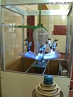
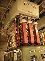
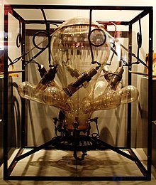
A rectifier used in high-voltage direct-current (HVDC) power transmission systems and in industrial processing between 1909 and 1975 is the mercury-arc rectifier or mercury-arc valve. The device is enclosed in a bulb-shaped glass vessel or a large metal tank. One electrode, the cathode, is submerged in a pool of liquid mercury at the bottom of the vessel, and one or more high-purity graphite electrodes, called anodes, are suspended above the pool. There may be several auxiliary electrodes for igniting and sustaining the arc. When an electric arc forms between the cathode pool and the suspended anodes, a flow of electrons travels from the cathode to the anodes through the ionized mercury, but not in the opposite direction (in principle, this is a more powerful analogue of flame rectification, which uses the same one-way current-conduction properties of plasma that are naturally present in a flame).
These devices could be used at power levels of hundreds of kilowatts and could be built to handle from one to six phases of alternating current. Mercury-arc rectifiers were replaced by silicon semiconductor rectifiers and high-power thyristor circuits in the mid-1970s. The most powerful mercury-arc rectifiers ever built were installed in the Manitoba Hydro Nelson River Bipole HVDC project, with a combined capacity of over 1 GW and 450 kV.[16] [17]
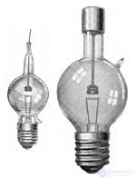
Made by General Electric, the Tungar rectifier was a gas-filled electron tube device filled with mercury vapor (e.g. 5B24) or argon (e.g. 328), with a tungsten-filament cathode and a carbon-button anode. It worked similarly to a thermionic vacuum-tube diode, but the gas in the tube ionized during forward conduction, giving it a much lower forward voltage drop, so it could rectify lower voltages. It was used for battery chargers and similar applications from the 1920s until it was displaced by cheaper metal rectifiers, and later by semiconductor diodes. They were rated for a few hundred volts and a few amperes and, in some sizes, closely resembled an incandescent light bulb with an extra electrode.
The 0Z4 was a gas-filled rectifier tube commonly used in tube-type car radios in the 1940s and 1950s. It was an ordinary full-wave rectifier tube with two anodes and one cathode, but it was unique in having no filament (hence the "0" in its type number). The electrodes were shaped so that the reverse breakdown voltage was much higher than the forward breakdown voltage. Once the breakdown voltage was exceeded, the 0Z4 switched into a low-resistance state with a forward voltage drop of about 24 V.
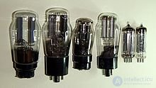
The thermionic vacuum-tube diode, originally called the Fleming valve, was invented by John Ambrose Fleming in 1904 as a detector for radio waves in radio receivers and evolved into a general-purpose rectifier. It consisted of an evacuated glass bulb with a filament heated by a separate current, and a metal anode plate. The filament emitted electrons through thermionic emission (the Edison effect), discovered by Thomas Edison in 1884, and a positive voltage on the plate caused a flow of electrons through the tube from the filament to the plate. Since only the filament generates electrons, the tube conducts current in only one direction, allowing the tube to rectify alternating current.
Thermionic diode rectifiers were widely used in the power supplies of vacuum-tube electronic devices such as phonographs, radio receivers, and televisions — for example the All American Five radio receiver — to provide the high DC plate voltage required by other vacuum tubes. Full-wave versions with two separate plates were popular because they could be used with a center-tapped transformer to make a full-wave rectifier. Vacuum-tube rectifiers were made for very high voltages, such as the high-voltage power supply for the cathode-ray tube of television receivers, as well as the kenotron used for power supply in X-ray equipment. However, compared to modern semiconductor diodes, tube rectifiers have a high internal resistance due to space charge and, as a result, high voltage drops that cause large power dissipation and low efficiency. They can rarely withstand currents above 250 mA because of the power-dissipation limits of their plates, and cannot be used for low-voltage devices such as chargers. Another limitation of the tube rectifier is that the heater power supply often requires special provisions to isolate it from the high voltages in the rectifier circuit.
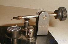
The crystal detector was the first type of semiconductor diode. Invented by Jagadish Chandra Bose and developed by G. W. Pickard starting in 1902, it was a significant improvement over earlier detectors such as the coherer. The crystal detector was widely used before the advent of vacuum tubes. One popular type of crystal detector, often called a cat's-whisker detector, consists of a crystal of some semiconducting mineral, usually galena (lead sulfide), with a light springy wire touching its surface. Its fragility and limited current-carrying capacity made it unsuitable for power supplies. In the 1930s, researchers shrank and improved the crystal detector for use at microwave frequencies.
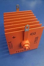
Once common, until they were replaced by more compact and less expensive silicon solid-state rectifiers in the 1970s, these devices used stacks of oxide-coated metal plates and took advantage of the semiconducting properties of selenium oxide or copper oxide.[18] Although selenium rectifiers were lighter in weight and consumed less power than comparable tube rectifiers, they had the drawback of a finite service life, increasing resistance with age, and were suitable for use only at low frequencies. Selenium and copper-oxide rectifiers withstand brief voltage surges somewhat better than silicon rectifiers.
Typically these rectifiers consisted of stacks of metal plates or washers held together by a central bolt, with the number of stacks determined by the voltage; each cell was rated at about 20 V. The rectifier of an automobile charger might have only one cell, while a high-voltage power supply for a vacuum tube might have dozens of stacked plates. The current density in an air-cooled selenium stack was about 600 mA per square inch of active area (about 90 mA per square centimeter).
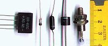
Silicon diodes are the most widely used rectifiers for lower voltages and powers and have largely replaced other rectifiers. Thanks to a significantly lower forward voltage (0.3 V compared to 0.7 V for silicon diodes), germanium diodes have an inherent advantage over silicon diodes in low-voltage circuits.
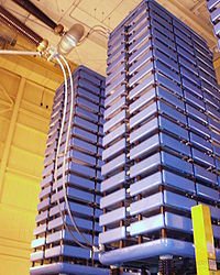
In high-power applications between 1975 and 2000, most mercury-arc rectifiers were replaced by stacks of very high-power thyristors, silicon devices with two additional semiconductor layers compared to a simple diode.
In medium-power transmission applications, even more complex and sophisticated systems of silicon semiconductor voltage-source converter (VSC) rectifiers, such as insulated-gate bipolar transistors (IGBTs) and gate turn-off thyristors (GTOs), made high-voltage direct-current power transmission systems more economical. All of these devices function as rectifiers.
As of 2009, it was expected that these high-power silicon "self-commutating switches," in particular IGBTs and a thyristor variant related to the GTO called the integrated gate-commutated thyristor (IGCT), would be scaled up in power to the point where they would eventually replace simple thyristor-based AC rectification systems for the highest-power direct-current transmission applications.[19]
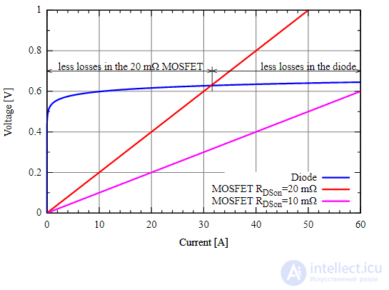
Active rectification is a technique for increasing rectification efficiency by replacing diodes with actively controlled switches, such as transistors, typically power MOSFETs or power BJTs.[20] Whereas ordinary semiconductor diodes have a roughly fixed voltage drop of about 0.5–1 volt, active rectifiers behave like resistances and can have an arbitrarily low voltage drop.
Historically, a vibrator-driven switch or motor-driven commutators have also been used for mechanical rectification and synchronous rectification.[21]
Active rectification has many applications. It is often used for arrays of photovoltaic panels to avoid the reverse current that can cause overheating under partial shading, with minimal power loss.
A major area of research is the development of high-frequency rectifiers capable of operating at terahertz and optical frequencies. These devices are used for optical heterodyne detection, which has many applications in fiber-optic communications and atomic clocks. Another promising application of such devices is the direct rectification of light waves captured by tiny antennas called nantennas, to produce direct-current electric power.[22] Arrays of antennas are believed to potentially be a more efficient means of generating solar power than solar cells.
A related area of research is the development of smaller rectifiers, since a smaller device has a higher cutoff frequency. Research projects are attempting to develop a single-molecule rectifier — a single organic molecule that could function as a rectifier.

Comments