
Lecture
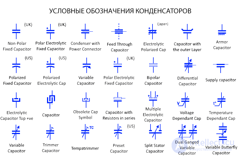
Symbols for capacitors depend on their type and the standard used (European or American). Here are the main symbols used in circuit diagrams:
Universal capacitor
A capacitor is an electronic component that stores energy in its electric field. This is the symbol for a general capacitor. It is a non-polarized capacitor with a fixed capacitance value. It can be connected in either direction. The second symbol is an older symbol for a capacitor, used for non-polarized capacitors.
Polarized electrolytic capacitor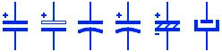
This type of capacitor uses an electrolyte as one of its electrodes, which is why it is polarized. It has positive and negative terminals, and the upper part of these symbols represents the positive terminal. A polarized capacitor must be connected to the circuit correctly, otherwise it will explode. The first two symbols are used in the UK, and the next two symbols in the USA. The fifth symbol for the capacitor is used in Japan.
Variable capacitor
This symbol represents a variable capacitance, whose capacitance can be changed during normal operation. The capacitance is changed by increasing or decreasing the effective area between the plates, which affects the capacitor's capacitance. They are used in LC tuning circuits.
Trimmer capacitor
This is also a variable capacitor, whose capacitance is used to calibrate a circuit during manufacturing or to troubleshoot the circuit. The capacitance of such a capacitor is usually not adjusted by users during operation.
Bipolar capacitor
These are also known as non-polarized electrolytic capacitors. They are made from two electrolytic capacitors in a construction that allows them to be used with either polarity. They differ from ordinary non-polarized ceramic capacitors in having a much higher capacitance.
Feedthrough capacitor
This type of capacitor is designed to supply DC power in radio-frequency systems. It delivers a clean DC signal while also filtering out any radio-frequency components from it.
Feedthrough (bushing) capacitor
Voltage-dependent capacitor
The capacitance of this type of capacitor depends on the applied voltage. Increasing or decreasing the supply voltage changes the size of the dielectric gap between the plates, which increases the capacitance.
Temperature-dependent capacitor
The capacitance of these capacitors depends on the ambient temperature. Raising or lowering the temperature can increase or decrease the capacitor's capacitance. They are used in temperature-measuring applications.
Differential capacitor
This is a variable capacitor with two working stators and one shared rotor. Moving the rotor increases the capacitance in one section while simultaneously decreasing it in the other section. However, the total capacitance remains the same.
Split-stator capacitor
As the name suggests, this type of variable capacitor has two sets of stators spaced 180° apart. A common shaft rotates the rotor, which has the same vanes spaced 180° apart. Such capacitors do not have the 90° limitation found in an ordinary variable capacitor.
Dual capacitor
This is a combination of two variable capacitors. The variable rotors of these two capacitors are controlled by a single shaft. In this way, moving one rotor provides variable capacitance in both capacitors.
Butterfly capacitor
This type of variable capacitor has two separate stators mounted opposite each other on the capacitor's housing. A rotor, whose plates are also shaped like a butterfly, rotates between these two stators. The capacitance in such a capacitor changes equally between the stator and the rotor. They are used in symmetrically tuned circuits.
Temperature trimmer
A temperature trimmer, also known as a thermal trimmer, is a small trimmer capacitor with a variable temperature coefficient. They are used to stabilize drifting VFOs.

Comments