
Lecture
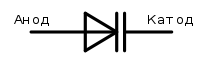
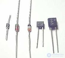
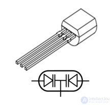
Varicap (an acronym from the English "vari(able)" — "variable", and "cap(acitance)" — "[electrical] capacitance") is an electronic device, a semiconductor diode, whose operation is based on the dependence of the barrier capacitance of a p-n junction on reverse voltage.
Varicaps with high dissipated power, designed for frequency multiplication in radio transmitters, are commonly called varactors.
Varicaps are used as elements with electrically controlled capacitance in circuits for tuning the frequency of a resonant circuit in frequency-selective networks, frequency division and multiplication, frequency modulation, controlled phase shifters, and others.
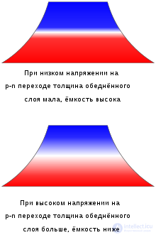
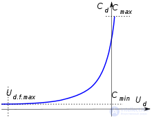
In the absence of an external voltage applied to the electrodes, a potential barrier and an internal electric field exist in the p-n junction, arising from the contact potential difference between the p-type and n-type semiconductors. The normal operating mode of a varicap is with reverse bias. If a reverse voltage is applied to the diode (that is, the cathode must have a positive potential relative to the anode), the height of this potential barrier increases. The external reverse voltage pushes electrons deeper into the n-region, resulting in an expansion of the depletion region of the p-n junction — that is, the layer of semiconductor depleted of charge carriers, which is essentially a dielectric. As the reverse voltage increases, the thickness of the depletion layer increases. This can be represented as a parallel-plate capacitor, in which the non-depleted regions of the semiconductor serve as the plates, with a variable dielectric layer thickness.
In accordance with the formula for the capacitance of a parallel-plate capacitor, as the distance between the plates increases (caused by an increase in reverse voltage), the capacitance of the p-n junction decreases. This decrease is limited by the thickness of the base, beyond which the thickness of the depletion layer cannot increase further; once this minimum capacitance is reached, the capacitance no longer changes with further increases in reverse voltage. Another limiting factor for controlled capacitance reduction is the electrical avalanche breakdown of the depletion layer.
Since the thickness of the dielectric (depletion layer) changes over a wide range as the reverse voltage varies, the dynamic  , or differential, capacitance — the capacitance for a small change in voltage across the device (a small-signal parameter) — is used to characterize the change in varicap capacitance with applied voltage. The dynamic capacitance is defined as :

where  is the increment of the capacitor's electric charge;
 is the increment of voltage.
According to GOST R 52002-2003, differential capacitance is the dynamic capacitance for a very slow change in voltage.
The dependence of dynamic capacitance on voltage is called the capacitance-voltage characteristic and is approximately described for a varicap by the function:
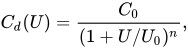
where  is the dynamic capacitance of the device at zero voltage;
 is the applied reverse voltage;
 is a certain constant having the dimension of voltage and approximately equal to the forward voltage of the p-n junction at small forward currents, which for a silicon device is about 0.55 V;
 is an exponent characterizing the magnitude of the doping concentration gradient in the p-n junction; for junctions with a smooth, for example linear, change in concentration
  , for abrupt junctions
  , and for junctions with step doping can reach 2 .
[[s|varicap]]
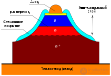
Varicaps are usually manufactured using planar-epitaxial technology, which allows optimization of the device's electrical parameters. On a wafer of heavily doped, low-resistivity semiconductor (usually of n-type conductivity, denoted n+), a high-resistivity film of lightly doped n-type semiconductor is grown. By diffusing an acceptor impurity, a low-resistivity p-type anode layer is formed on the surface of the epitaxial layer.
The lateral surface of the structure is coated with a low-melting-point glass to protect the p-n junction where it reaches the surface and to increase the reverse breakdown voltage.
Varicaps are manufactured both as discrete components (for example, varicaps produced in the USSR and Russia, KV105, KV109, KV110, KV114, BB148, BB149) and as varicap assemblies (for example, KVS111).
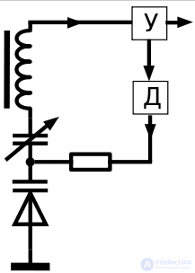
Varicaps are used for tuning the frequency of voltage-controlled oscillators in frequency synthesizers and sweep-frequency generators, for tuning voltage-controlled frequency-selective circuits, in automatic frequency control systems of various radio receiving devices, in parametric amplifiers, for frequency multiplication in voltage-controlled frequency multipliers, in phase shifters, and others.
A semiconductor diode whose operating principle is based on the dependence of the electrical junction's capacitance on reverse voltage is called a varicap. A varicap is essentially an electrically controlled capacitance. Varicaps are manufactured based on silicon and gallium arsenide. The capacitance of varicaps varies over a wide range, and its dependence on reverse voltage differs for varicaps made by the diffusion method versus the alloying (fusion) method of introducing impurities.
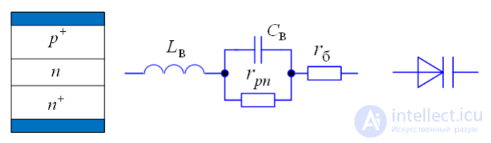
Varicap with structure 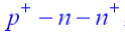 , equivalent circuit, and standard graphical symbol of a varicap
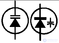
Varactor (from the English "variable" and "act" — action, "actor" — one that acts) is an electronic device, a semiconductor diode whose reactance depends on the applied reverse voltage. The precise definition is ambiguous.
The term "varactor" is defined differently by different authors. In Russian-language literature, many specialists regard it as a synonym for, or a special case of, a varicap. This view is so widespread that no separate circuit symbol for the varactor, distinct from the varicap, has been devised. Sometimes the word "varactor" is not used at all, and only the term "varicap" is employed. This may be related to the absence of the term "varactor" from the state standards of the Soviet Union and post-Soviet states.
There are, however, a number of distinct opinions that define the concept of "varactor" in their own way, and some authors even consider it to be a broader term than "varicap".
The understanding of the term "varactor" and its relationship to the term "varicap" in English-language literature, as well as in literature in other languages, requires clarification.
Many consider a varactor to be a varicap . In this case, often only the term varicap is used. But there are also authors who use only the term varactor. There is also the form varactor diode.
At the same time, there is a definition of a varactor as a subtype of varicap — a multiplier diode , that is, one used for frequency multiplication . The same "Metalworker's Handbook" notes that varactors are used in the microwave range in parametric amplifiers. Yu. A. Ovechkin , on the other hand, does not use the term "varactor" but also calls similar varicaps parametric. GOST 15133-77[10] does the same.
Thus, a parametric diode is a varactor/varicap used in parametric amplifiers.
It is also worth mentioning that there are authors who use both terms without defining them, and from context it is not always clear whether they are equivalent or not[11].
In descriptions of circuit diagrams, two names are sometimes given[12], but this may be related to the interchangeability of different types of diodes due to the particular features of a specific circuit. This requires clarification.
This view appears in a recently published textbook of Southern Federal University (SFU)[13]. The authors prefer the term "varactor" and explain that it is more general than the term "varicap", which came from low-frequency electronics.
The authors distinguish subtypes of the varactor depending on the purpose of its use in circuits:
This point of view was expressed by a group of authors in 1973[14]. The authors distinguish the varactor from the varicap by field of application and by a feature of the p-n junction's operation. However, they explain that their definition is not universally accepted, and that many people understand a varactor to be simply a varicap intended for operation in the microwave range.
More specifically, in their understanding, varactors are designed to operate at large amplitudes, such that during part of the signal oscillation period the p-n junction is in the forward-conducting (open) state. In this case, the barrier capacitance of the junction, in the course of its turning on, can increase by several orders of magnitude due to the addition of what is called diffusion capacitance.
As a result, the differential capacitance of the p-n junction ceases to depend significantly on the degree of nonlinearity of the capacitance of the closed p-n junction, which is determined by its chemical composition. Thus, reducing this degree of nonlinearity does not degrade the operation of the varactor, unlike the varicap, and can sometimes even be beneficial, since it speeds up the process of restoring the closed state of the p-n junction and, consequently, reduces power losses.
The authors therefore note a trend, in the design of new varactors, toward reducing the degree of nonlinearity almost to zero through the use of p-i-n junctions. In this case, the voltage-charge (coulomb-volt) characteristic of the varactor approaches a piecewise-linear function.
This point of view is in some respects similar to the opinions of other authors[15][16], who consider that varactors make use of the nonlinear properties of the p-n junction, unlike varicaps, which use only the linear properties, although the remaining properties of the two coincide.

Comments