
Lecture
Here are the main symbols for generators and alternators used in electrical schematics:
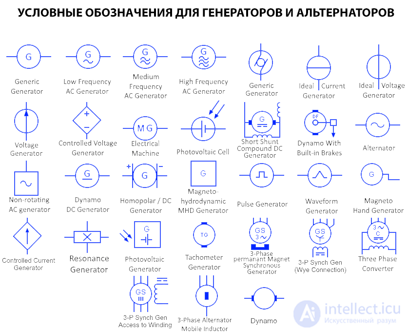
At the end of this article is a list showing all the corresponding generator and alternator symbols in a single image.
General generator symbol
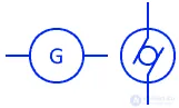
This symbol represents a simple generator. A generator converts mechanical energy into electrical energy.
Low-frequency AC generator
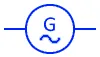
Generators of this type produce alternating current at a very low frequency range, from 8 Hz to 40 Hz. They are mainly used in traction systems operating at 16.7 Hz. Low-frequency generators are useful for transmitting electric power over long distances.
Medium-frequency AC generator
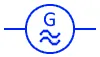
The alternating current produced by this generator falls within the standard household range of 50 to 60 Hz.
High-frequency AC generator
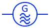
These generators produce alternating current at frequencies above 100 Hz. Since transmission losses increase with frequency, they are used in enclosed spaces. Power systems at 400 Hz are used in military equipment, spacecraft, aircraft, and server rooms.
Ideal current generator

This symbol represents an ideal current generator. The current produced by an ideal current generator is constant, while the voltage can vary.
Ideal voltage generator

An ideal voltage generator provides a constant voltage, while the current it produces can vary depending on the connected load. The symbol represents an ideal voltage generator.
Voltage generator

This is the symbol used for a voltage generator. A voltage generator generates and maintains a voltage across its terminals. Its voltage does not depend on other elements in the circuit and does not change with the current drawn from it.
Controlled voltage generator
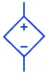
This is a dependent voltage generator, whose terminal voltage depends on other elements of the circuit or on the current drawn from its terminals.
Electric machine

This type of symbol is used for machines that can operate as both a motor and a generator. A motor converts electrical energy into mechanical energy, while a generator does the opposite.
Photovoltaic / solar cells

A photovoltaic cell, or solar cell, converts light energy into electrical energy. It is the building block of a solar panel, where these solar cells are connected in series and in parallel to increase its overall voltage and current.
Short-shunt DC generator

The shunt field winding is connected in parallel with the armature, while the series field winding is connected in series with the load. The shunt field winding has high resistance, so that current flows toward the load.
Dynamo with built-in brake

A dynamo is an electric machine that generates direct current by means of commutation. A dynamo consists of a rotor and a stator made of coils. The rotor rotates inside the constant magnetic field created by the stator coil and produces an EMF. It has a built-in braking system to stop its rotation when you want to switch it off.
AC generator

An AC generator is an electric generator that converts mechanical energy into alternating current. In an AC generator, the rotating magnetic field of the rotor generates alternating current in the stator (armature) winding.
Non-rotating AC generator

This symbol represents a non-rotating AC generator / alternator. The square symbol represents the stationary part of the generator.
Dynamo / DC generator

This symbol represents a DC generator, also known as a dynamo. It converts mechanical energy into direct current by means of a commutator.
Unipolar DC generator

A unipolar generator operates by rotating a conducting disk inside a magnetic field, which creates a direct current between the center and the rim of the disk. It generates low voltage but high current.
Magnetohydrodynamic / MHD generator

This is a DC generator that converts thermal and kinetic energy into DC electrical energy. It has no moving parts. Hot ionized plasma (which is a conductor) moves within a magnetic field, which generates a DC potential difference along opposite electrodes. In addition, the exhaust gases can also be used for steam power plants.
Pulse generator

A pulse generator is an electronic circuit that generates rectangular pulses. It has a variable frequency, amplitude, and duty cycle to meet the requirements of its applications. It is a very common piece of test equipment used for testing any digital circuit, most often as a clock signal.
Waveform generator

A waveform generator is also an electronic circuit that generates various waveforms. The most common waveforms are the square wave, triangular wave, sawtooth wave, etc. It provides a variable frequency with a variable duty cycle. The generated waveforms are used to trigger or stimulate any circuit or signal processing.
Hand-cranked magneto generator

A magneto is an electric generator that produces alternating current by rotating a coil inside a permanent magnet. Unlike a dynamo, it has no commutator, so its output is alternating current, and the rotor is rotated by means of a hand crank.
Controlled current generator
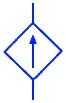
This symbol represents a controlled current generator, also known as a dependent current generator. It is a generator, or current source, whose value depends on other elements of the circuit.
Photovoltaic generator

This is the symbol for a solar-powered generator, which converts solar energy into electrical energy. It consists of a solar panel, a charge controller, and a battery. The usable solar energy is converted into DC and AC electrical energy by means of inverters for consumption purposes.
Tachometer generator

This symbol represents a tachometer generator. It produces a voltage depending on the rotational speed of its shaft. It is thus used to measure the speed of motors.
3-phase permanent-magnet synchronous generator

The output frequency of a synchronous generator depends on the speed of the rotor. This is a 3-phase synchronous generator that uses a permanent magnet. The rotor rotates inside the constant magnetic field created by the permanent magnet instead of a coil, inducing an EMF within the rotor windings.
3-phase star/star-connected synchronous generator

This symbol represents a star- (wye-) connected synchronous generator. Three-phase AC generators connected in a star configuration require fewer winding turns than those connected in delta. In addition, the neutral point, if grounded, is used as a path for zero-sequence current during a fault (unbalanced conditions).
3-phase converter

This symbol represents a 3-phase converter. It can convert a single-phase AC electrical input into a 3-phase electrical output and vice versa. These are mainly used to operate three-phase electrical equipment from a single-phase AC supply by converting it into three-phase AC.
Three-phase synchronous generator with access to each winding

This is the symbol for a 3-phase AC synchronous generator in which each winding is accessible. The terminals of each winding are brought out for connection.

Comments