
Lecture
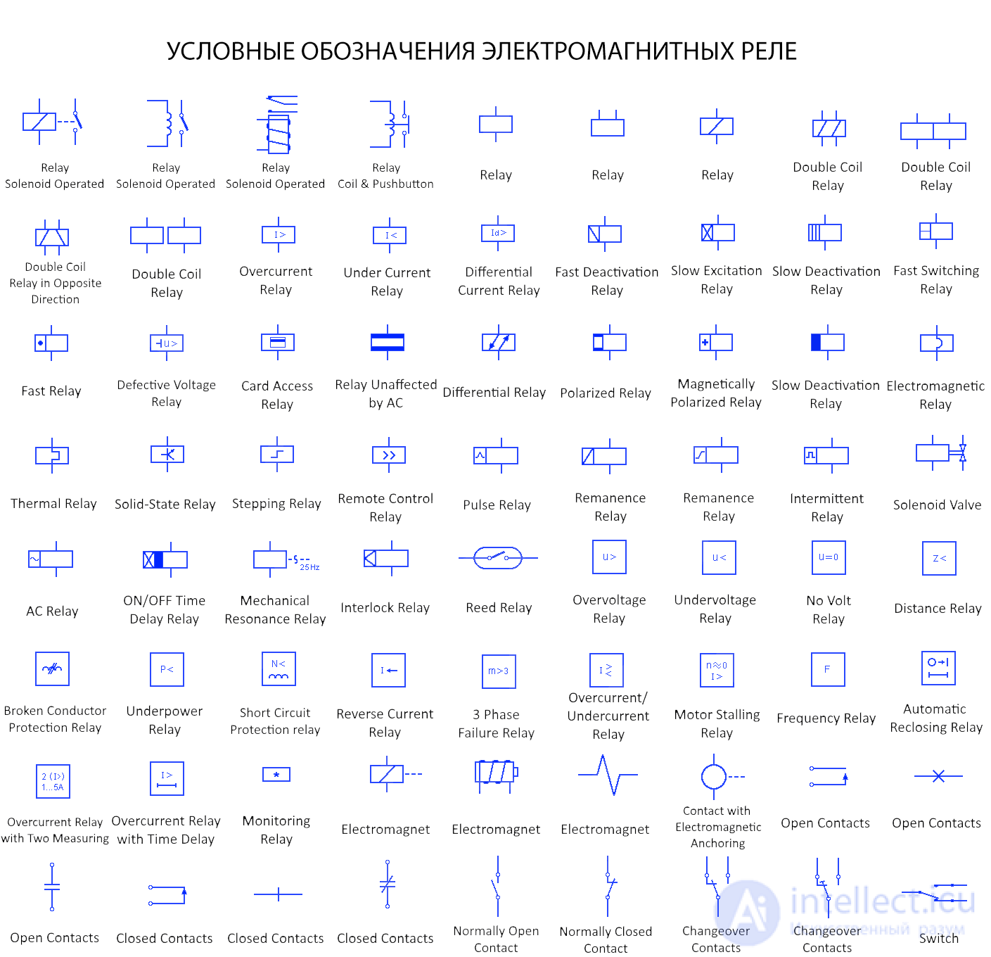
The symbols used for electromagnetic relays in electrical diagrams vary depending on the type of relay, its contacts, and its coil. Here are the basic symbols:
Solenoid-Operated Relay
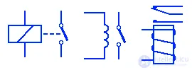
A solenoid relay has a coil wound around a core, which creates a magnetic field when the coil is energized by current flowing through it. The magnetic field pulls the armature (movable contact) to either close or open the contact.
Solenoid Relay with a Button

This relay has a button instead of an armature. The energized coil pulls in the button, closing or opening the contact.
Universal Relay
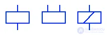
A relay is an electrical switch that has a set of control terminals and contact terminals. The control terminals are controlled by one or more control signals to switch the contact terminals. They are used to switch relatively high-power circuits using low-power signals.
Dual-Coil Relay
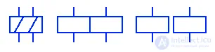
This type of relay has two coils. Each coil has separate control terminals. Either of the two coils is used to close or open the contact. When coil 1 is energized, it closes the contact, while energizing coil 2 opens the contact. Dual-coil relays are mostly latching devices, whose contacts remain in their position even after the coil is de-energized.
Dual-Coil Relay with Opposite Winding Direction

This type of dual-coil relay has windings directed opposite to each other. The magnetic field created by one coil opposes the field of the other. Each coil changes the contact position when power is applied.
Overcurrent Relay

An overcurrent relay is a protective relay that activates when the current exceeds a limit, in order to protect the system. It mainly isolates the system from a short-circuit current by breaking the contact between them.
Undercurrent Relay

This is also a current protection relay, used to protect a system or circuit from low current. It activates when the current drops below a specified limit.
Differential Current Relay

A differential relay operates on the phase difference between the input and output current of a system. If there is any difference, it indicates the presence of a short-circuit current, so it begins to switch. These are used to protect transformers, feeders, motors, and so on.
Fast Deactivation Relay

As the name suggests, this type of relay has a very fast release speed. As soon as power to the coil is cut off, the coil is immediately de-energized and thus switches the contact.
Slow Pickup Relay

This type of relay has an inertial coil. When the coil is energized, there is a time delay before the contact terminals switch.
Slow Release Relay
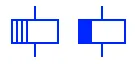
This type of relay has a time delay when power is removed from its control terminals. A capacitor is connected in parallel, which keeps the coil energized for a certain time depending on its characteristics. After the capacitor discharges, the coil is de-energized and switches the contacts.
Fast Switching Relay
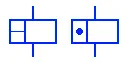
This is a fast-switching relay that can instantly switch from the activated state to the deactivated state very quickly and vice versa. The coil of such a relay turns on or off as soon as power is applied or removed, respectively. They are used for instantaneous switching.
Voltage Fault Relay

This type of protective relay is activated by a voltage fault in the line. When a voltage fault occurs in the line that could damage equipment, the relay activates to prevent such damage.
Card Access Relay

This is an electronic relay that operates using special cards. Most card access relays are wireless relays that identify the card and transmit a signal to the relay wirelessly to activate or deactivate it. They are used for security purposes.
AC-Immune Relay

This type of relay coil is not affected by alternating current.
Differential Relay

Differential relays operate on the difference between two electrical quantities. They activate when the specified difference exceeds or falls below a fixed limit. Most differential relays are protective relays used to protect systems.
Polarized Relay

A polarized relay is a type of relay whose switching depends on the direction of the current flowing through the coil. Some relays have magnetic polarization, others use a diode connected in series with the coil, which prevents current from flowing in the reverse direction.
Magnetically Polarized Relay

Polarized relays consist of an electromagnetic coil and a permanent magnet. The magnetic flux of the coil distorts the magnetic flux of the permanent magnet to switch the contacts to one of the positions. These relays mainly have three positions. It is usually in a neutral position, and the direction of the current switches it to one of the two other positions.
Electromagnetic Relay

This type of relay has an electromagnetic coil that is powered by either AC or DC. The coil creates a magnetic field that attracts the armature (contact) to close or open the contact.
Thermal Relay

This type of relay operates based on temperature. It has a bimetallic strip that bends under the effect of heat. A heat-generating element inside the relay, due to high current, bends the metal strip to break or close the contact. They are used to protect machines from overload.
Solid-State Relay

A solid-state relay (SSR) is a type of relay made from semiconductors that uses an optocoupler to switch the main circuit. It has no moving or mechanical parts, so it has a longer service life, since mechanical contacts wear out with switching. There is no switching noise or vibration or motion effect on its operation.
Stepping Relay

A stepping relay is a type of relay that directs the input current through one of many output terminals using a series of control pulses. The pulses move the contact arm, rotating it step by step to connect it to one of the many output terminals.
Remote Control Relay

This type of relay is controlled by a wireless remote control. These relays allow a user or any system to control it without any physical or electrical connection. These relays can turn on/off or switch to one of several outputs depending on their type.
Pulse Relay

A pulse relay is a type of latching relay that is activated by a voltage pulse. It retains its position, i.e. OFF or ON, until another voltage pulse appears.
Remanence Relay
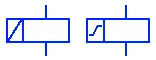
A remanent-field relay, or remanence relay, is a type of latching relay that retains its position due to the residual magnetic field in the core. The core is de-energized when current flows in the reverse direction.
Intermittent Relay

This type of relay has a time-delay function. Once activated, its contacts close after a fixed time and then open again. It repeats the cycle until power is cut off.
Solenoid Valve

A solenoid valve is an electromechanical valve used to regulate the flow of a fluid or to switch the fluid flow to other ports. There are various types of solenoid valves depending on the current and their mechanism.
AC Relay

As the name suggests, the coil of this relay is powered only by alternating current. The alternating current creates a varying magnetic field in the coil, which attracts the contact terminal.
On/Off Time Delay Relay

This is the symbol for a relay that has a time-delay function for both activation and deactivation. The contacts of such relays turn on and off with an adjustable time delay to provide power pulses. A blinking light is a classic example of an application of a time delay relay.
Mechanical Resonance Relay
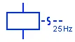
This type of relay detects mechanical resonance in a system and activates when resonance occurs. Mechanical resonance is a phenomenon in which the mechanical frequency becomes equal to the system's natural frequency. In this case, the resonant frequency is 25 Hz.
Interlocking Relay

An interlocking relay consists of two or more coils with individual contacts, where the operation of one coil depends on the position of the contacts of the other coils.
Reed Relay
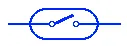
A reed relay consists of a magnetic contact enclosed in a tube filled with inert gas. The contacts are enclosed within an electromagnetic coil. The contact closes when the coil is energized or if there is an external magnetic field. It is very fast and sensitive to weak currents, but has very low current and voltage ratings.
Overvoltage Relay

This type of protective relay is used to protect against overvoltage. It trips when the voltage exceeds the relay's specified voltage limit.
Undervoltage Relay

This is also a protective relay, but it activates when the voltage level drops below a set limit. It protects the circuit from low voltage.
No-Voltage Relay

This type of voltage-protection relay detects the presence of voltage. When the voltage is removed, it activates. It is used in motor starters to increase resistance when voltage is removed, so that the motor does not automatically start with low armature resistance (which could damage it).
Distance Relay

A distance relay, or impedance relay, operates based on the impedance between a fault in the line and the point where it is installed. The impedance is measured from the current and voltage ratings supplied by CTs and PTs. As soon as the impedance drops below the relay's impedance limit, the relay activates.
Broken Conductor Protection Relay

This type of protective relay is used to detect a broken conductor in a three-phase power system. It operates based on the ratio of the positive-sequence current (I1) to the negative-sequence current. The ratio increases significantly when a phase breaks, and the relay activates the alarm system.
Power Relay

This type of protective relay monitors the power supply. As soon as the power drops below its threshold value, it activates to open or close the contact.
Coil Short-Circuit Protection Relay

This relay detects a short circuit between the turns of coils and activates a protective measure to prevent further damage to the systems.
Reverse Current Relay

This type of relay opens the contacts when current flows in the reverse direction. It is used in DC generators: when the battery voltage is higher than the generator voltage, the relay opens to stop the battery from discharging.
3-Phase Failure Detection Relay

This is a protective relay used for three-phase loads, such as a motor or other equipment, to prevent it from starting up and being damaged or burned out due to a broken phase or failure of any phase.
Overcurrent/Undercurrent Relay

This protective relay is used to protect against low or high current. As long as the current stays within limits, the relay does not activate, but as soon as the current crosses either limit (fault current), the contacts open, protecting the circuit.
Motor Stall Relay

Stalling is a condition in which the windings are energized but the rotor does not rotate. During stalling, the motor draws a large current, which can cause overheating. This occurs due to a heavy load at startup or loss of a phase. The stall relay protects the motor from such a condition.
Frequency Relay

This type of relay operates based on the power system frequency. They are used to detect and protect against abnormal frequencies (under-frequency and over-frequency) in generators, etc. If the frequency exceeds or drops below a specified limit, it activates to switch the contacts.
Automatic Reclosing Relay

This type of relay can automatically reclose after opening due to a power failure. They are used in power systems where a fault might clear itself after the failure. If the fault still persists, the relay locks the contacts in the open position after several attempts.
Time-Delayed Overcurrent Relay

This type of current protection relay adds a time-delay function. They are used in power systems that can withstand high current for a short period of time. If the current remains high for a certain period of time, the relay opens the contact.
Monitoring Relay

This type of protective or signaling relay monitors or measures electrical quantities and protects circuits from them when they exceed their limit. The asterisk is replaced by the symbol of that quantity. Types of monitoring relays include overvoltage/overcurrent relays, undervoltage/undercurrent relays, and so on.
Electromagnet
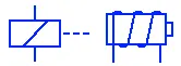
An electromagnet is a wire wound into a coil around a magnetic core. Current flowing through the coil creates a magnetic field, which is strengthened by the magnetic core. It is used in relays to actuate the contact terminals.
Open Contacts
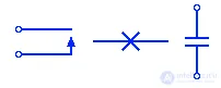
These are symbols used to represent open relay contacts. This means the contact is open and no current flows.
Closed Contacts
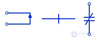
These symbols represent closed contacts, or a closing contact. The contacts are shorted and current can flow through them.
Normally Open Contact
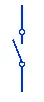
This symbol represents relay contacts that are open when there is no power. The circuit is broken and there is no current. When the relay is activated, the contacts close and it begins to conduct current.
Normally Closed Contact

This is a relay contact that is in the closed position when there is no power. The contacts open when the relay is activated, breaking the circuit.
Changeover Contact
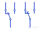
This is a relay changeover contact that is closed, or connected to one terminal (known as the normally closed terminal), when the relay is deactivated, while the other terminal is open (known as the normally open terminal). It changes the contact position when the relay is activated.
Switch
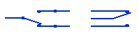
These two symbols represent the switching part of a relay, which is used to turn current on/off or switch it from one terminal to another.

Comments