
Lecture
Poynting vector (also Umov—Poynting vector) — the energy flux density vector of the electromagnetic field, whose components are part of the energy-momentum tensor of the electromagnetic field .
The Poynting vector S can be defined through the cross product of two vectors:
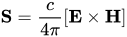 (in the CGS system),
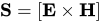 (in the International System of Units (SI)),
where E and H — are the electric and magnetic field strength vectors respectively. In SI the quantity S has the dimension of W/m2.
|
Derivation for SI
|
|---|
|
Let an electromagnetic wave propagate in vacuum (
In vacuum, Then Multiplying the last expression by |
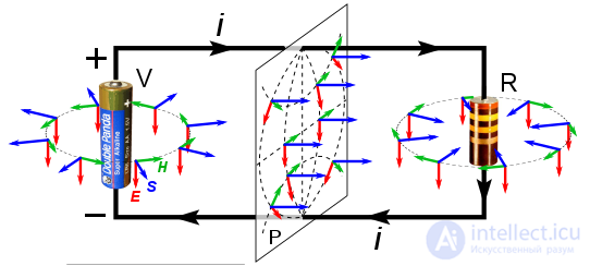
direct current circuit i, connecting a battery V to a resistor R
Poynting vector S in the space surrounding the circuit
electric field strength E
magnetic field strength H
Around the battery the Poynting vector is directed away from the battery, indicating the transfer of energy from the battery; around the resistor the Poynting vector is directed toward the resistor, indicating the transfer of energy into the resistor; the flux of the Poynting vector through any plane P between the battery and the resistor — is directed from the battery to the resistor.
In the case of quasi-monochromatic electromagnetic fields, the following formulas are valid for the period-averaged complex energy flux density :
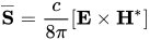 (in the CGS system),
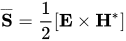 (in the SI system),
where E and H — are the vectors of the complex amplitude of the electric and magnetic fields respectively. In this case only the real part of the complex vector S has a clear physical meaning — this is the vector of the period-averaged energy flux density. The physical meaning of the imaginary part depends on the specific problem.
The magnitude of the Poynting vector equals the amount of energy transferred through a unit area normal to S per unit time. The direction of the vector determines the direction of energy transfer.
Since the tangential components of E and H at the boundary between two media are continuous (see boundary conditions), the normal component of the vector S is continuous at the boundary between two media.
Owing to the symmetry of the energy-momentum tensor, all three components of the spatial momentum density vector of the electromagnetic field are equal to the corresponding components of the Poynting vector divided by the square of the speed of light:
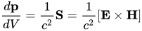 (in the SI system)
This relation reveals the materiality of the electromagnetic field.
Therefore, to find the momentum of the electromagnetic field in a given region of space, it is sufficient to integrate the Poynting vector over the volume.
In a macroscopic medium, electromagnetic effects are described by spatially averaged (macroscopic) fields. The Poynting vector in a macroscopic medium can be defined self-consistently with the microscopic theory in such a way that the spatially averaged microscopic Poynting vector is exactly predicted by the macroscopic formalism. This result is strictly valid in the limit of small losses and makes it possible to unambiguously identify the form of the Poynting vector in macroscopic electrodynamics. [5
A general concept of the flow of mechanical energy in space was first introduced by N. A. Umov in 1874 for elastic media and viscous liquids. On this basis, in older Russian-language publications the energy flux density vector of any physical nature is called the Umov vector . In 1884, J. H. Poynting developed the concept of the density of electromagnetic energy flux. Therefore the density vector of the flux of electromagnetic energy is called the Poynting vector.
The very laws of conservation and transformation of energy, in which the concept of the flux density of some type of energy is present, are usually used without indicating the names of their discoverers, since conservation laws are a consequence of other equations and additional conditions.
Poynting's theorem (eng. Poynting's theorem) — a theorem describing the law of conservation of energy of the electromagnetic field. The theorem was proved in 1884 by John Henry Poynting. It all comes down to the following formula:
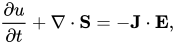
where  — is the energy density:
 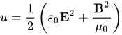 ;
;
 — the electric constant,
  — the magnetic constant;
 — the nabla operator; S — the Poynting vector;
J — the current density and E — the electric field strength.
Poynting's theorem in integral form:
 ,
,
where  — is the surface bounding the volume
  .
.
In the technical literature the theorem is usually written as follows ( — energy densities):
 ,
,
where  — is the energy density of the electric field,
  — is the energy density of the magnetic field and
  — is the power of Joule losses per unit volume.
The theorem can be derived using two of Maxwell's equations (for simplicity we assume the medium is vacuum (μ=1, ε=1); for the general case with an arbitrary medium, it is necessary to append ε and μ to each ε0 and μ0 in the formulas):
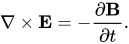
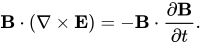
Multiplying both sides of the equation by  , we obtain:
Let us first consider the Maxwell–Ampere equation:
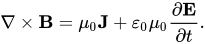
Multiplying both sides of the equation by  , we obtain:

Subtracting the first from the second, we obtain:

Finally:

Since the Poynting vector  is defined as:
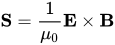
this is equivalent to:

The mechanical energy of the theorem described above

where u_m — is the kinetic energy density in the system. It can be described as the sum of the kinetic energy of particles α

 — energy flux, or the «mechanical Poynting vector»:

The energy continuity equation, or the law of conservation of energy

Other forms of Poynting's theorem can also be obtained. Instead of using the flux vector  one can choose the Abraham form
  , the Minkowski form
  , or some other.
A connection between the configuration of the fields and the Umov vector also exists in the case of variable fields, when the electric and magnetic fields change in time. As before, at each given moment the Umov vector is directed perpendicular to the electric and magnetic field strength vectors (by the right-hand screw rule), and its absolute magnitude is proportional to the product of the absolute magnitudes of the field strengths.
If the length of a two-wire line is small compared to the wavelength of the alternating current feeding it, then the picture of energy propagation differs little from the picture of energy propagation with direct current.
For a short line length, during the time it takes for the electric field to run from the beginning to the end of the line, the voltage at its beginning hardly has time to change. Therefore, at each given moment the voltage between the wires along the entire length of the line turns out to be approximately the same.
When the source and the load do not have reactance, the voltage and current in the line coincide in phase, which means the electric and magnetic fields around the line also change in the same phase.
In this case the vectors E and H simultaneously pass through zero and reverse their direction in space, hence the Umov vector does not change its direction in space.
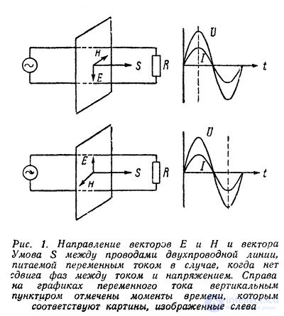
Two instantaneous pictures, corresponding to two different directions of the vectors E and H, are shown in Fig. 1.
Thus, despite the fact that the electric and magnetic fields change their direction in space twice per period, the energy flows all the time in one direction from the emf source to the load, just as in the case of direct current.
The difference lies only in the fact that with direct current the Umov vector remains constant in time both in magnitude and direction (just as the vectors E and H do), while with alternating current the Umov vector periodically changes in magnitude, reaching a maximum and falling to zero twice per period (just as the product of the absolute magnitudes of the vectors E and H does), but not changing its direction in space.
This means that whereas with direct current the flow of energy along the line does not change with time, in the case of alternating current it pulsates in time.
A different picture is obtained in the case when there is a phase shift between the voltage and the current in the line and, consequently, the changes in the electric and magnetic fields are shifted in phase. This occurs when the load or the emf source has not only resistance but also reactance.
Let us first consider the imaginary case when the load represents a purely reactive resistance, and the source and the line have no resistance. Then the phase shift between the voltage and the current in the line will equal 90° and the changes in the vectors E and H will occur with the same phase shift.
In this case the changes in the directions of the vectors E and H will not occur simultaneously, but with a time shift of a quarter period. But whenever only the vector E or only the vector H reverses its direction, the Umov vector also reverses its direction. This means the Umov vector will change its direction four times per period.
Fig. 2 shows two instantaneous pictures, corresponding to different directions of the Umov vector.
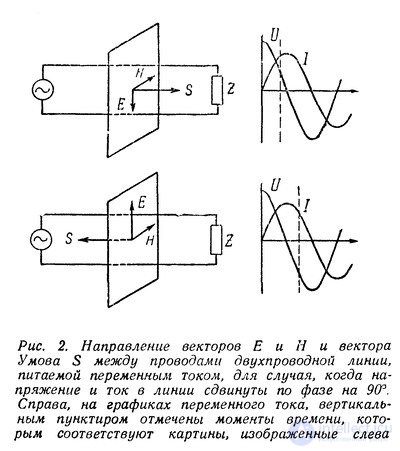
The Umov vector will, in addition, also change in magnitude in accordance with the change in the product of the absolute magnitudes of the vectors E and H.
Continuing the same construction as in Fig. 2 for the next two quarters of the period, it is easy to verify that during the first and third quarters of the period the energy flow is directed from the emf source to the load, and during the second and fourth quarters — from the load to the source. In this case, the amount of energy flowing in each direction is the same. This means that the energy flow averaged over the period at any cross-section of the line is equal to zero.
This result is fully consistent with the fact that a purely reactive resistance does not consume energy from the source. During a quarter of the period it accumulates energy coming from the source, and during the other quarter of the period it returns all this energy to the source.
In real cases, the load, the emf source and the line always have resistance. Therefore the phase shift between the voltage and the current in the line, and hence between the changes in the vectors E and H, is always less than 90°. In this case the Umov vector still changes its direction to the reverse four times per period.
But unlike the previous case, the time during which it is directed in one direction or the other turns out to be different: for a greater amount of time it is directed toward the side corresponding to identical signs of E and H. (This is easy to verify by making the same constructions as in Fig. 2, for the case when the phase shift is less than 90°).
Under these conditions, the amount of energy flowing in both directions is no longer the same, but different; more energy flows from the source to the load than back. On average over the period the energy still flows from the source to the load, although for part of the period it flows from the load to the source. This is fully consistent with the fact that a load having both resistance and reactance does not consume all the energy received from the source over the period, since it returns part of the energy back to the source. Since a real line has resistance, then, as in the case of a direct-current line, a longitudinal electric field appears. As a result of this, the field lines bend forward, the Umov vectors deflect toward the wires, and part of the energy flows into the wires, being dissipated in them as heat.
 ) and let its speed equal
  . Then the total electromagnetic energy density will be made up of the energy densities of the electric field and the magnetic field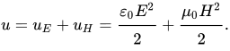
 and
and  change in phase, hence it can be assumed that

 we obtain for the magnitude of the energy flux density

Comments