
Lecture
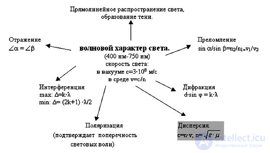
In this section we will consider some effects that arise when light propagates in a medium. The first of them — polarization — is related to the transverse anisotropy of light waves, that is, to the nonequivalence of different directions in the plane perpendicular to the light ray. Next we will analyze the phenomenon of dispersion of light, which manifests itself in the dependence of the phase velocity of light wave propagation in a medium on frequency (wavelength). Finally, we will briefly touch upon absorption and scattering of light in a medium.
A consequence of Maxwell's theory is the transversality of electromagnetic (light) waves propagating in vacuum or an isotropic medium: the vectors of electric and magnetic field strength of the wave are mutually perpendicular and oscillate perpendicular to the velocity vector v of wave propagation (that is, perpendicular to the light ray). The phenomenon of light polarization serves as reliable evidence for the transversality of the light wave. When considering polarization, all reasoning is usually related to the plane of oscillation of the electric field strength vector E — the light vector, since chemical, physiological and other effects of light on matter are due mainly to electric oscillations. However, one should remember the obligatory existence of the magnetic field strength vector perpendicular to it, H.
Polarization of an electromagnetic wave. Writing the solution for the electric field of a plane electromagnetic wave in the form
|
|
|
(6.1) |
we assumed that the direction of the oscillation amplitude vector  does not depend on time. In this case, the electric field vector is always, at every point of the wave, directed along one and the same straight line — it oscillates in a single plane of fixed orientation in space.
|
The plane in which the oscillations of the light vector occur, that is, the plane containing the vector |
Choosing the axis x along the direction of wave propagation, and the axis y — along the amplitude vector  , we write (6.1) in the form
|
|
|
(6.2) |
However, there also exists a second linearly polarized wave having the same frequency and propagating in the same direction:
|
|
|
(6.3) |
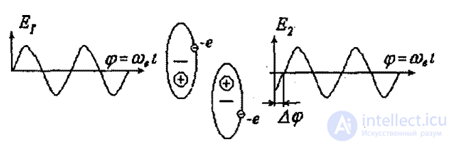
Electric oscillations in this wave are directed along the axis z, so that waves (6.2) and (6.3) are linearly independent. Both of them are solutions of one and the same wave equation, so their superposition is also a solution of the same equation. By adding these waves, we obtain the general expression for a monochromatic wave of given frequency w, propagating along the axis x. Mathematically this procedure is no different from adding mutually orthogonal oscillations. If we fix some point x and follow the change of the electric field vector there, the tip of the vector  will trace out, in the general case, an elliptical, trajectory in a plane parallel to y0z. The rotation of the vector
  occurs at the wave frequency
  . In this case the light is said to have elliptical polarization. If the phase difference
  is a multiple of
  , the elliptical polarization degenerates into linear. When the amplitudes E0,y and E0,z are equal, the ellipse becomes a circle. This is then called circular polarization of the wave. According to the two possible directions of rotation of the vector
  , there are possible right- and left-polarized waves. Any electromagnetic wave can be represented as a linear combination of two linearly polarized waves or as a linear combination of two circularly polarized waves. In other words, electromagnetic waves have two internal degrees of freedom.
Natural and polarized light. In light emitted by ordinary sources, there are oscillations occurring in various directions perpendicular to the ray. In such light waves, emanating from various elementary emitters (atoms), the vectors  have different orientations, all of these orientations being equally probable, which is due to the large number of atomic emitters. Such light is called natural, or unpolarized.
If, under the influence of external effects on the light or internal features of the light source (laser), a preferred, most probable direction of oscillation appears, such light is called partially polarized. Unpolarized (natural) light can only be emitted by a huge number of elementary emitters. An electromagnetic wave from a single elementary emitter (atom, molecule) is always polarized. Using various polarizers, one can select from a beam of natural light a part in which the oscillations of the vector  occur in one definite direction in the plane perpendicular to the ray, that is, the selected light will be linearly polarized.
In figures, the direction of oscillation of the electric field of a linearly polarized wave is depicted as follows. If the vector E oscillates in the plane of the drawing, then on the direction of the wave velocity vector  a series of vertical arrows is drawn (Fig. 6.1-1), and if in the plane perpendicular to the drawing — a series of dots (Fig. 6.1-2). Natural (unpolarized) light is conventionally denoted by alternating dashes, corresponding, for example, to the component Ey of the electric field strength vector, and dots, corresponding to the other component Ez (Fig. 6.1-3).
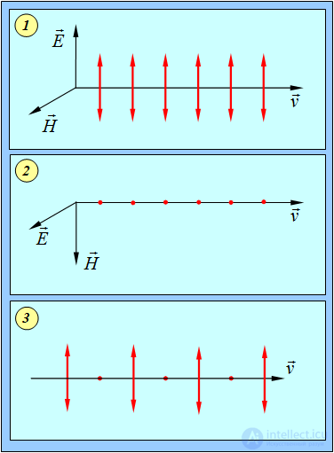
Fig. 6.1. Conventional notation for the type of wave polarization
There exist devices (polarizers) that pass only oscillations occurring parallel to a certain plane, called the plane of polarization of the device, and completely block orthogonal oscillations. If a beam of light is passed through such a device, it will be linearly polarized at the output. When the device is rotated about the direction of the ray, the intensity of the outgoing light will vary from IMAX to IMIN.
|
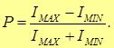
Degree of polarization of light is the quantity
|
Note that formula (6.4) is suitable for calculating the degree of polarization of light only in the case when the partially polarized light is a mixture of natural light and linearly polarized light, and does not work, for example, in the case of a mixture of natural light and circularly polarized light. In the general case, the degree of polarization can be calculated as the ratio of the intensity of the polarized component  to the total intensity of the wave, that is, to the sum of the intensities of the polarized
  and natural
  components of the mixture:

It is not difficult to show that (6.4) is a special case of the last formula.
If the incident light beam is linearly polarized, then in the position of the device where its plane of polarization is orthogonal to the plane of oscillation of the wave, light will not pass through the device, that is,  . According to formula (6.4), the degree of polarization of such light is
  . For partially polarized light

and  . For natural light, where waves of different polarizations are mixed in equal degree and all directions are equivalent, the intensity of the outgoing light does not change when the polarizer is rotated, so that
  and
and  .
.
Malus's law. Media anisotropic with respect to oscillations of the vector E, for example natural tourmaline crystals, can be used as polarizers. A tourmaline single crystal absorbs oscillations of the vector E in one direction so strongly that only a linearly polarized ray passes through a plate about 1 mm thick. Iodoquinine sulfate crystals absorb one of the polarizations even more strongly: a crystalline film a tenth of a millimeter thick almost completely separates out one of the linearly polarized rays.
Let natural light propagate perpendicular to the plane of figure 6.2.
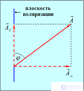
Fig. 6.2. Decomposition of the oscillation amplitude vector A in the wave incident on the polarizer
The vector  of the amplitude of the electric field oscillations of the wave, occurring in a plane that forms an angle
  with the plane of the polarizer, can be decomposed into two oscillations with amplitudes

The first oscillation with amplitude A|| passes through the device (polarizer), the second — with amplitude A — will be blocked (absorbed). The intensity of the transmitted wave is proportional to the square of the amplitude
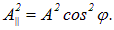
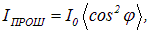
The incident wave is a mixture of waves with various angles  . Averaging over the angles, we obtain for the intensity of light at the output of the polarizer:
|
|
|
(6.5) |
where  — is the intensity of the light incident on the polarizer. In natural light, all values of the angle
  are equally probable:
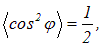
so that the intensity of the light transmitted through the polarizer will be equal to  . When the polarizer is rotated about the direction of the natural light ray, the intensity of the transmitted light remains unchanged, but only the orientation of the plane of oscillation of the light emerging from the device changes.
Let us now consider the incidence of linearly polarized light with intensity  on the same polarizer (Fig. 6.3).
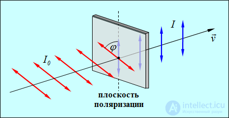
Fig. 6.3. Passage of a linearly polarized wave through a polarizer
Video 6.1 Polarizer and analyzer for a decimeter wave.
Video 6.2 Polarizer and analyzer for a three-centimeter wave.
The component of oscillation with amplitude

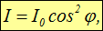
where  — is the angle between the plane of oscillation of the vector E and the plane of the polarizer. Consequently, the intensity of the transmitted light I is determined by the expression
|
|
|
(6.6) |
which is known as Malus's law.
Video 6.3 Polarizer and analyzer for visible light — 2
Video 6.4 Natural visible light. Three polarizers. Malus's law.
By their intended purpose, polarizing devices are divided into polarizers and analyzers. Polarizers serve to obtain polarized light. With the help of an analyzer, one can verify that the incident light is polarized and determine the direction of the plane of polarization. There is no fundamental difference in construction between a polarizer and an analyzer.
Let us place in the path of natural light two polarizers, the planes of which form an angle  (Fig. 6.4).
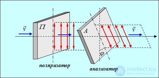
Fig. 6.4. Transmission of natural light through a system of two polarizers
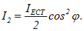
From the first polarizer, linearly polarized light will emerge, whose intensity  , will amount to half the intensity of the incident natural light
  . According to Malus's law, from the second polarizer (which plays the role of an analyzer) light will emerge with intensity
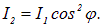
Thus, the intensity of the light transmitted through the two polarizers is equal to
|
|
|
(6.7) |
If the angle  (the planes of polarization of the polarizer and analyzer are parallel), then
  ; if
; if  (the analyzer and polarizer are crossed), then
  .
.
Example 1. In partially polarized light, the oscillation amplitude corresponding to the maximum intensity of light passing through a polarizer is n = 2 times greater than the amplitude corresponding to the minimum intensity. Let us determine the degree of polarization of the light.
Since the intensity is proportional to the square of the amplitude, we have
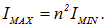
From this, the degree of polarization of the light is equal to

Example 2. An analyzer was placed in the path of light with degree of polarization P = 0.6 so that the intensity of the transmitted light became maximal. Let us determine by what factor the intensity will decrease if the analyzer is turned by an angle  ?
?
In the incident ray, by condition (see the previous example)
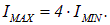
When the analyzer is turned through an angle  , the oscillations parallel to the plane of polarization of the device will be transmitted. Therefore, the intensity of the transmitted oscillations, previously parallel to the plane of polarization, will be
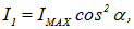
and the intensity of the transmitted oscillations, previously blocked by the analyzer before the rotation, is equal to
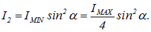
The total intensity of the transmitted oscillations is equal to the sum
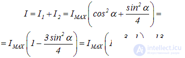
Hence, the intensity will decrease when the analyzer is turned by a factor of 16/13 = 1.23 times.
Polarization on reflection and refraction. Polarized light can be obtained from natural light in another way as well — by reflection. Experiment shows that the rays reflected from and refracted by the surface of a dielectric are always partially polarized. When light falls on a dielectric surface, oscillations perpendicular to the plane of incidence predominate in the reflected ray (dots in Fig. 6.5), while in the refracted ray oscillations parallel to the plane of incidence predominate (arrows in Fig. 6.5).
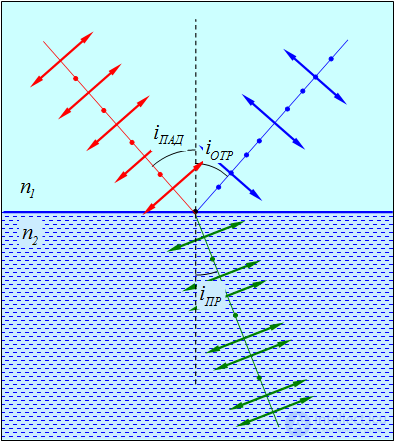
Fig. 6.5. Polarization of light on reflection and refraction
Video 6.5 Polarization of natural light on reflection from glass.
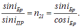
The degree of polarization depends on the angle of incidence of the rays and on the relative refractive index of the media. Investigating this phenomenon, the English physicist D. Brewster established that at a certain value of the angle of incidence

satisfying the condition
|
|
|
(6.8) |
the reflected light is completely polarized in the plane perpendicular to the plane of incidence of the ray. This relation is known as Brewster's law. At

only that component of the electric field strength vector which is parallel to the surface of the dielectric (perpendicular to the plane of incidence) is reflected. Accordingly, the refracted ray is always partially polarized, since only some fraction of the incident light is reflected (not equal to 50 %).
|
When light is incident at the Brewster angle, the reflected and refracted rays are mutually perpendicular, the reflected light is completely polarized in the plane perpendicular to the plane of incidence of the ray, and the refracted ray is partially polarized with the maximum degree of polarization. |
Video 6.6 The Brewster angle.
Indeed, at

we find, taking into account the law of refraction,
|
|
|
(6.10) |
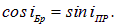
From this we obtain
|
|
|
(6.11) |
Thus,

from which it follows that the refracted ray 0C is perpendicular to the reflected ray 0B (Fig. 6.6).
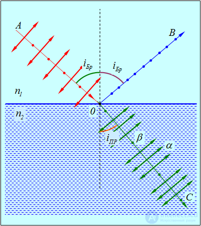
Fig.6.6. Path of the rays when light is incident at the Brewster angle: the reflected ray is orthogonal to the refracted ray,
therefore emitters of type  (see text below) do not contribute to the polarization of the reflected ray
To explain why the ray reflected at incidence at the Brewster angle is linearly polarized in the plane perpendicular to the plane of incidence, note that reflected light is the result of the radiation of secondary waves by electric charges (electrons), oscillating under the action of the light vector of the wave, in medium II. These oscillations occur in the direction of oscillation of the vector E.
Let us decompose the oscillations of the vector E in medium II into two mutually perpendicular directions (see Fig. 6.6): oscillations  , occurring in the plane of incidence (shown by arrows), and oscillations
  , occurring perpendicular to the plane of incidence (shown by dots). In the case of incidence at the Brewster angle

the reflected ray 0B is perpendicular to the refracted ray 0C. Consequently, 0B is parallel to  . From Maxwell's electromagnetic theory it is known that an oscillating electric charge does not radiate electromagnetic waves along the direction of its motion. Therefore an emitter of type
  , oscillating in the dielectric, does not radiate along the direction 0B . Thus, in the direction of the reflected ray 0B , light propagates that is sent only by emitters of type
  , whose directions of oscillation are perpendicular to the plane of incidence.
It should be noted that in experiment Brewster's law is not satisfied quite strictly, owing to the dispersion of light.
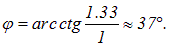
Example 3. Let us determine at what angular height  above the horizon the Sun must be for sunlight, reflected from the surface of water, to be completely polarized.
The angle of incidence of the light is related to the height of the Sun above the horizon by the relation

By condition, the angle of incidence equals the Brewster angle, so that

The refractive indices are: water n2 = 1.33, air — n1 = 1. From this we find
Example 4. The Brewster angle for light incident from air on a rock-salt crystal is  . Let us determine the speed of light V in this crystal.
Since the refractive index of air is equal to unity, the refractive index of rock salt n coincides with the relative refractive index  of these two media. We therefore have

|
Dispersion of light — is the dependence of the refractive index n of a substance on the wavelength of light (in vacuum)
|
or, equivalently, the dependence of the phase velocity of light waves on frequency:
|
|
|
(6.13) |
|
Dispersion of a substance is the name given to the derivative of n with respect to
|
Dispersion — the dependence of the refractive index of a substance on the frequency of the wave – manifests itself especially vividly and beautifully together with the effect of double refraction (see Video 6.6 in the previous section), observed when light passes through anisotropic substances. The point is that the refractive indices of the ordinary and extraordinary waves depend differently on the frequency of the wave. As a result, the color (frequency) of light passed through an anisotropic substance placed between two polarizers depends both on the thickness of the layer of this substance and on the angle between the transmission planes of the polarizers.
Video 6.8 Dispersion and anisotropy: mica plates between polarizers.
Video 6.9 Dispersion and anisotropy: polymer film between polarizers.
Video 6.10 Dispersion and anisotropy: a CD-disc blank.
Video 6.11 Dispersion and anisotropy: a loaded «beam».
Video 6.12 Dispersion and anisotropy: crumpled cellophane wrapper.
Video 6.13 Dispersion and anisotropy: a mica butterfly and…
For all transparent colorless substances, in the visible part of the spectrum, the refractive index increases as the wavelength decreases, that is, the dispersion of the substance is negative:  . (Fig. 6.7, regions 1-2, 3-4)
|
Normal dispersion of a substance — is negative dispersion
|
If a substance absorbs light in some range of wavelengths (frequencies), then in the absorption region the dispersion

turns out to be positive and is called anomalous (Fig. 6.7, region 2–3).
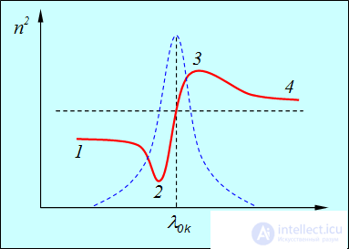
Fig. 6.7. Dependence of the square of the refractive index (solid curve) and the absorption coefficient of light by the substance
(dashed curve) on the wavelength l near one of the absorption bands ( )
)
Normal dispersion was studied as early as Newton. The decomposition of white light into a spectrum on passing through a prism is a consequence of the dispersion of light. When a beam of white light passes through a glass prism, a multicolored spectrum appears on the screen (Fig. 6.8).
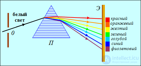
Fig. 6.8. Passage of white light through a prism: owing to the difference in the values of the refractive index of glass for different
wavelengths, the beam is decomposed into monochromatic components — a spectrum appears on the screen
Red light has the longest wavelength and the smallest refractive index, so red rays are deflected by the prism less than others. Next to them will be rays of orange, then yellow, green, cyan, blue and, finally, violet light. The complex white light incident on the prism has been decomposed into monochromatic components (a spectrum).
A striking example of dispersion is the rainbow. A rainbow is observed if the sun is behind the observer's back. Red and violet rays are refracted by spherical droplets of water and reflected from their inner surface. Red rays are refracted less and reach the observer's eye from droplets located at a greater height. Therefore, the upper band of the rainbow always turns out to be red (Fig. 26.8).
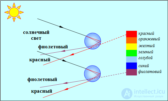
Fig. 6.9. Formation of a rainbow
Using the laws of reflection and refraction of light, one can calculate the path of light rays under total reflection and dispersion in raindrops. It turns out that the rays are scattered with the greatest intensity in a direction forming an angle of about 42° with the direction of the solar rays (Fig. 6.10).
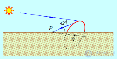
Fig. 6.10. Position of the rainbow
The geometric locus of such points is a circle centered at the point 0. Part of it is hidden from the observer P below the horizon, and the arc above the horizon is the visible rainbow. Double reflection of the rays in raindrops is also possible, leading to a second-order rainbow, whose brightness is, naturally, less than the brightness of the primary rainbow. For it, theory gives an angle of 51°, that is, the second-order rainbow lies outside the primary one. In it, the order of colors is reversed: the outer arc is colored violet, and the lower one — red. Rainbows of the third and higher orders are rarely observed.
Elementary theory of dispersion. The dependence of the refractive index of a substance on the wavelength (frequency) of the electromagnetic wave is explained on the basis of the theory of forced oscillations. Strictly speaking, the motion of electrons in an atom (molecule) obeys the laws of quantum mechanics. However, for a qualitative understanding of optical phenomena, one can limit oneself to the picture of electrons bound in an atom (molecule) by an elastic force. When displaced from the equilibrium position, such electrons begin to oscillate, gradually losing energy to the radiation of electromagnetic waves or transferring their energy to lattice nodes and heating the substance. As a result, these oscillations will be damped.
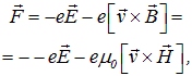
When passing through a substance, the electromagnetic wave acts on each electron with the Lorentz force:
|
|
|
(6.15) |
where v — is the speed of the oscillating electron. In an electromagnetic wave, the ratio of the strengths of the magnetic and electric fields is equal to
|
|
|
(6.16) |
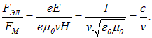
Therefore it is not difficult to estimate the ratio of the electric and magnetic forces acting on the electron:
|
|
|
(6.17) |
Electrons in a substance move at speeds much smaller than the speed of light in vacuum:

Thus, one can consider that when an electromagnetic wave passes through a substance, only the electric force acts on each electron:
|
|
|
(6.18) |
where  — is the amplitude of the electric field strength in the light wave,
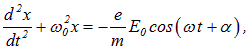
  — is the phase of the wave, determined by the position of the electron under consideration. To simplify the calculations, we neglect damping and write the equation of motion of the electron in the form
|
|
|
(6.19) |
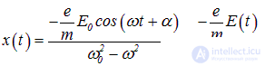
where  — is the natural frequency of oscillation of the electron in the atom. We have already considered the solution of such an inhomogeneous differential equation earlier and obtained
|
|
|
(6.20) |
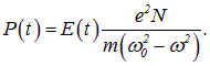
Consequently, the displacement of the electron from the equilibrium position is proportional to the electric field strength. The displacements of nuclei from the equilibrium position can be neglected, since the masses of nuclei are very large compared with the mass of the electron.
An atom with a displaced electron acquires a dipole moment
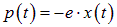
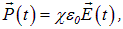
(for simplicity, let us assume for now that the atom has only one «optical» electron, whose displacement makes the dominant contribution to the polarization). If a unit volume contains N atoms, then the polarization of the medium (dipole moment per unit volume) can be written in the form
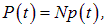
|
|
|
(6.21) |
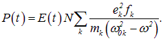
In real media, various types of oscillations of charges (groups of electrons or ions) contributing to the polarization are possible. These types of oscillations may have different charge magnitudes ei and masses mi, as well as different natural frequencies  (we will denote them by the index k), while the number of atoms per unit volume with a given type of oscillation Nk is proportional to the atomic concentration N:

The dimensionless proportionality coefficient fk characterizes the effective contribution of each type of oscillation to the total polarization of the medium:
|
|
|
(6.22) |
On the other hand, as is known,
|
|
|
(6.23) |
where  — is the dielectric susceptibility of the substance, which is related to the permittivity e by the relation
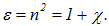
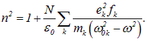
As a result we obtain an expression for the square of the refractive index of the substance:
|
|
|
(6.24) |
Near each of the natural frequencies  , the function
  , determined by formula (6.24), has a discontinuity. Such behavior of the refractive index is due to the fact that we have neglected damping. Similarly, as we saw earlier, neglecting damping leads to an infinite growth of the amplitude of forced oscillations at resonance. Taking damping into account frees us from the infinities, and the function
  has the form shown in Fig. 6.11.
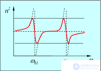
Fig. 6.11. Dependence of the permittivity of the medium  on the frequency of the electromagnetic wave
Taking into account the relation of the frequency to the wavelength of the electromagnetic wave in vacuum 

or

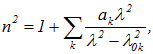
one can obtain the dependence of the refractive index of the substance n on wavelength in the region of normal dispersion (sections 1–2 and 3–4 in Fig. 6.7):
|
|
|
(6.25) |
where

— are the wavelengths corresponding to the natural oscillation frequencies  ,
,  — are constant coefficients.
In the region of anomalous dispersion ( ), the frequency of the external electromagnetic field is close to one of the natural oscillation frequencies of the molecular dipoles, that is, resonance occurs. It is precisely in these regions (for example, section 2–3 in Fig. 6.7) that significant absorption of electromagnetic waves is observed; the absorption coefficient of light by the substance is shown by the dashed line in Fig. 6.7.
The concept of group velocity. Closely related to the phenomenon of dispersion is the concept of group velocity. When real electromagnetic pulses propagate in a medium with dispersion, for example, the wave trains familiar to us that are emitted by individual atomic emitters, they undergo «spreading» — an expansion of their extent in space and duration in time. This is because such pulses are not a monochromatic sinusoidal wave, but a so-called wave packet, or group of waves — a collection of harmonic components with different frequencies  and different amplitudes, each of which propagates in the medium with its own phase velocity (6.13).
If the wave packet propagated in vacuum, its shape and space-time extent would remain unchanged, and the propagation velocity of such a wave train would be the phase velocity of light in vacuum
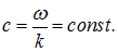
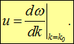
Because of the presence of dispersion, the dependence of the frequency of the electromagnetic wave on the wave number k becomes nonlinear, and the propagation velocity of the wave train in the medium, that is, the energy transport velocity, is determined by the derivative

where  — is the wave number for the «central» wave in the train (possessing the greatest amplitude).
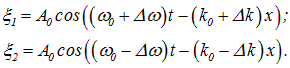
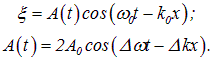
We will not derive this formula in general form, but will explain its physical meaning using a specific example. As a model of a wave packet, let us take a signal consisting of two plane waves propagating in the same direction with equal amplitudes  and initial phases
  , but differing in frequency, shifted relative to the «central» frequency
  by a small amount
  . The corresponding wave numbers are shifted relative to the «central» wave number
  by a small amount
  . These waves are described by the expressions:
|
|
|
(6.26) |
For the resulting wave

after applying the trigonometric formula for the sum of two cosines, we obtain the expression:
|
|
|
(6.27) |
We see that the resulting wave can be represented as a plane wave with the «central» frequency  and wave number
  , whose amplitude A(t) is a slowly varying (owing to the smallness of the shifts
  and
and  ) function of time and coordinate. A similar result was obtained earlier in the study of beats. It can be seen that this variable amplitude itself is a plane wave propagating with the velocity

In the limit of infinitesimally small frequency shifts, we arrive at the formula under discussion
|
|
|
(6.28) |
This velocity is called the group velocity. Since, as we already know, the energy of oscillations is determined by their amplitude, the «displacement» of the latter means that the group velocity is the velocity at which energy is transported by the wave packet.
The phase velocity of the wave, in turn, is the ratio of the frequency to the wave number:
|
|
|
(6.29) |
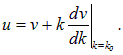
Differentiating this relation with respect to k, we find the connection between the phase and group velocities:
|
|
|
(6.30) |
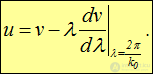
Taking into account the relation between the wave number and the wavelength

formula (6.30) can be rewritten as
|
|
|
(6.31) |
Obviously, in the absence of dispersion

the group velocity does not differ from the phase velocity.
The group velocity, as the velocity of energy propagation in a medium, cannot be greater than the speed of light in vacuum, that is, it is always  , whereas the phase velocity of light in a medium is not a limiting quantity and may turn out to be less than the velocity of particles moving in the medium, for example, electrons. In this case, as we already know, Cherenkov — Vavilov radiation arises.
The spreading of wave packets as they propagate in a dispersive medium can be understood if we imagine a compact group of a sufficiently large number of marathon runners setting off at the same time, which, on approaching the finish line, turns because of the runners' differing speeds into a group of athletes spread out in space, whose finishing times will characterize the temporal spreading of this analogue of a wave train. Thus, as a wave packet moves through a medium as a whole with the group velocity, its individual wave components move within the packet — since the different «participants» of the process move with different «phase» velocities.
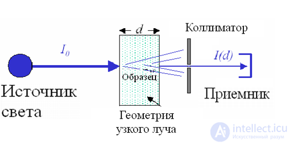
A light wave carries the energy of the electromagnetic field. As light passes through a substance, energy is lost as it is converted into various forms of the internal energy of the substance or into the energy of secondary radiation, which may differ from the primary radiation in its spectral composition and direction of propagation. Absorption of light can lead to heating of the substance or to the excitation of atoms and molecules, to photochemical processes, and so on.
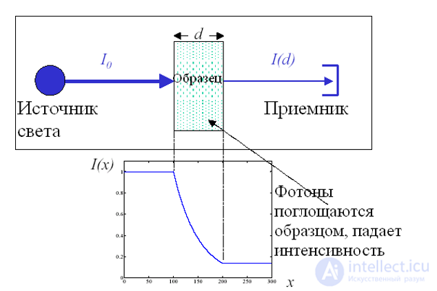
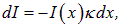
If a light wave with intensity at a given point I(x) passes through a layer of thickness dx, then its intensity decreases by an amount proportional to the thickness of the layer and the intensity of the wave at that point:
|
|
|
(6.32) |
where  — is the absorption coefficient, which depends on the properties of the absorbing substance.
Let us transform the resulting differential equation:

and integrate it
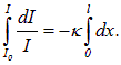
As a result of integration we obtain
|
|
|
(6.33) |
where I0 — incident light flux, I — thickness of the absorbing layer of the substance. This relation is called the Bouguer law — Lambert — Beer. It is valid for monochromatic light.
Relation (6.33) can be written in the form
|
|
|
(6.34) |
where
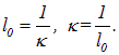
From this the physical meaning of k follows; the absorption coefficient is inversely proportional to the thickness of the layer of substance, on passing through which the intensity of light decreases by a factor of e = 2.72.
Resonant absorption occurs at frequencies close to the natural frequencies; energy is transferred from the acting field to the atoms of the substance, and the amplitude of their oscillations increases significantly. The charged particles of the medium are set into oscillatory motion by the electric field of the acting wave and re-emit light of the same frequency as the primary wave.
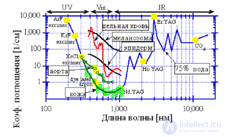
ABSORPTION OF LIGHT BY BIOLOGICAL TISSUES
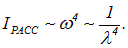
We observe a red Sun at sunset and a blue sky on a clear day. These phenomena can be explained by the scattering of light on density fluctuations of the gas making up the atmosphere — air. polarizes the gas, as a result of which each small volume of it, with a linear size smaller than or of the order of the wavelength, acquires a time-varying electric dipole moment and itself becomes a source of radiation whose frequency equals the frequency - of the incident light. The «trick» is that the intensity of the secondary – waves radiated by the gas is proportional to the fourth power of their frequency. That is, blue light is scattered an order of magnitude more intensely than red light. During the day, looking at the sky, we see scattered blue light. At sunrise or sunset we see light that has passed through the atmosphere, enriched with the weakly scattered long-wavelength red component. A more detailed discussion follows below.
In radiation theory, based on Maxwell's equations, it is shown that the power of secondary radiation is proportional to the square of the acceleration of a charged particle. If electrons oscillate under the action of a light wave according to the law

then their acceleration
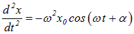
proportional to the square of the frequency  . Accordingly, the power of the secondary radiation is proportional to the fourth power of the frequency. Therefore the intensity of the scattered light is also proportional to the fourth power of the frequency, or inversely proportional to the fourth power of the wavelength of light — Rayleigh's law:
|
|
|
(6.35) |
Consequently, red and orange light are scattered much more weakly than blue and violet light, which is why the sky appears blue on a clear day. At sunset, sunlight passes through the greatest thickness of the atmosphere. A significant part of the blue radiation is scattered and does not reach the observer's eye. Therefore the transmitted ray reaching the Earth's surface loses its blue and violet components and consequently appears reddish.
It should be noted that Rayleigh's law holds only when the scattering objects are smaller than the wavelength of light. But, for example, clouds contain droplets of water and ice crystals whose size considerably exceeds the wavelength. A large number of such particles scatter light almost uniformly at all frequencies, mainly owing to the reflection of light from the surfaces of these particles, rather than actual scattering, if by that we mean the radiation of secondary waves. Since the reflection coefficient is practically independent of frequency, snow, clouds, and salt in a salt shaker all appear white.
Besides Rayleigh scattering there are other scattering processes, in particular ones involving a change in the frequency of the scattered light, such as Raman scattering of light, which will be considered later.
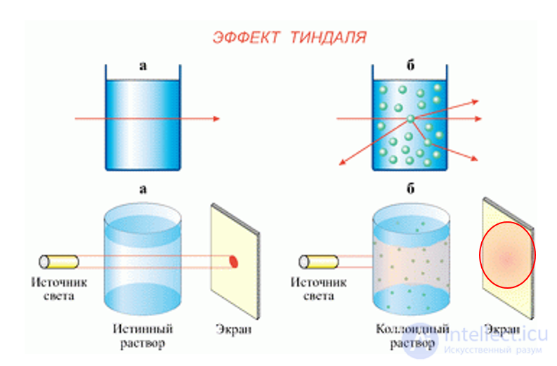
The Tyndall effect, Tyndall scattering (English: Tyndall effect) — an optical effect, the scattering of light as a light beam passes through an optically inhomogeneous medium. It is usually observed in the form of a glowing cone (the Tyndall cone), visible against a dark background.
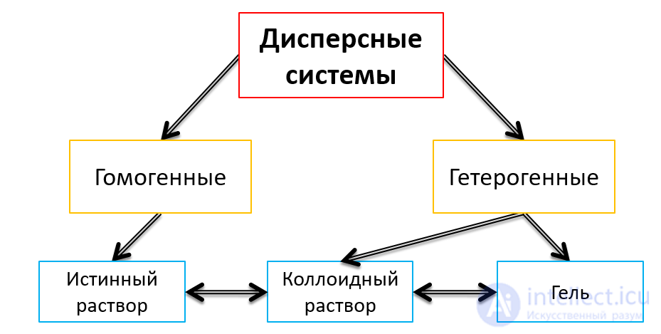
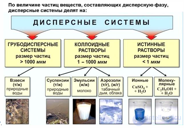
It is characteristic of solutions of colloidal systems (for example, metal sols, diluted latexes, tobacco smoke), in which the particles and the surrounding medium differ in refractive index. A number of optical methods for determining the size, shape, and concentration of colloidal particles and macromolecules are based on the Tyndall effect.
The Tyndall effect is the luminescence of an optically inhomogeneous medium due to the scattering of light passing through it. It is caused by the diffraction of light on individual particles or elements of structural inhomogeneity of the medium, whose size is much smaller than the wavelength of the scattered light. It is characteristic of colloidal systems (for example, hydrosols, tobacco smoke) with a low concentration of dispersed-phase particles having a refractive index different from that of the dispersion medium. It is usually observed in the form of a bright cone on a dark background (the Tyndall cone) when a focused light beam is passed sideways through a glass cell with plane-parallel walls filled with a colloidal solution. The short-wavelength component of white (non-monochromatic) light is scattered by colloidal particles more strongly than the long-wavelength component, so the Tyndall cone formed by it in a non-absorbing sol has a bluish tint. The Tyndall effect is essentially the same as opalescence. However, traditionally the first term refers to intense scattering of light in a confined region along the path of the beam, while the second refers to weak scattering of light throughout the entire volume of the observed object.
The Tyndall effect is perceived by the naked eye as a uniform glow of a certain part of the volume of the light-scattering system. The light comes from individual points — diffraction spots — that are clearly distinguishable under an optical microscope with sufficiently strong illumination of a diluted sol. The intensity of the light scattered in a given direction (for constant parameters of the incident light) depends on the number of scattering particles and their size.

Sunbeams passing through fog
Similar phenomena that are not Tyndall scattering
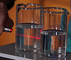
How can one determine whether a liquid has the properties of a sol? This is determined on the basis of the Tyndall effect: when a thin beam of light (for example, the beam of a laser pointer) passes through a colloidal solution, the light is scattered, and the beam takes on the shape of a cone. In the photograph, scattering occurs in the egg-white solution (the far glass), while in the table-salt solution in the near glass no scattering is observed
When the daytime sky is overcast with clouds, sunlight passes through the turbid layer of clouds, as a result of which scattered light (a sunbeam) appears on the ground. This demonstrates Mie scattering instead of Tyndall scattering, because cloud droplets are larger than the wavelength of light and scatter all colors approximately equally. When the daytime sky is cloudless, the color of the sky is blue because of Rayleigh scattering, not Tyndall scattering, because the scattering particles are air molecules, which are much smaller than the wavelength of visible light. [10]Likewise, the term Tyndall effect is incorrectly applied to the scattering of light by large macroscopic dust particles in the air; however, owing to their large size, they do not exhibit Tyndall scattering
Opalescence [opal + Latin escentia («weak action», glow)] — a physical phenomenon of light scattering by a turbid medium, caused by its optical inhomogeneity; observed, for example, when illuminating most colloidal solutions, as well as in substances in the critical state (critical opalescence).
Critical opalescence — an optical phenomenon of a sharp increase in the scattering of light by pure liquids and gases on reaching the critical point, as well as by solutions at critical mixing points. The cause is a sharp increase in the compressibility of the substance, accompanied by an intensification of density fluctuations (including of microparticles in solutions), on which the scattering of light occurs.
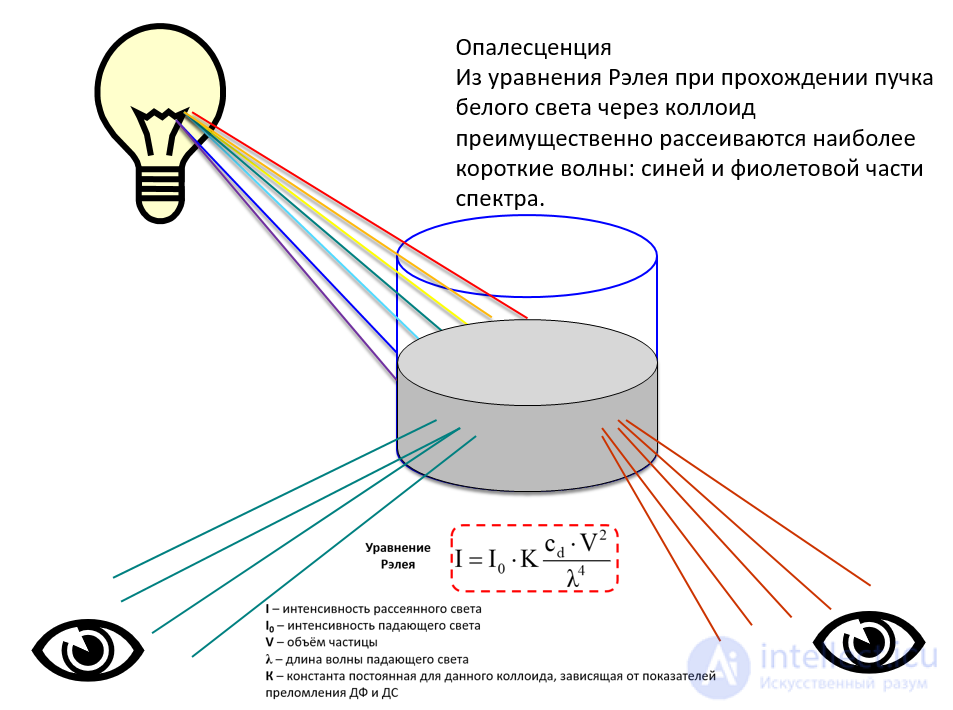
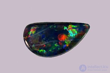
opalescence of a black opal
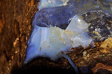
Rayleigh scattering in a white opal
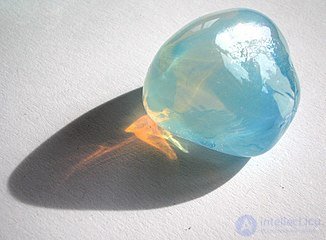
Rayleigh scattering
in opalescent glass:
it is orangish when viewed with light passing through it, and bluish when viewed from other directions. The same holds for diluted milk, white smoke, and the like.

 and the direction of wave propagation, is called the plane of oscillation. If this plane does not change its orientation in time, the wave is called — linearly (plane) polarized.










Comments