
Lecture
The phenomenon of electromagnetic induction was discovered in 1831 by M. Faraday (Fig. 8.1) and J. Henry (Fig. 8.2). The essence of this phenomenon lies in the symmetry between electric and magnetic interactions. If a current is passed through a loop placed in a magnetic field, a torque begins to act on the loop, turning it. What will happen if we turn the loop in a magnetic field instead? Will an electric current not arise as a result? As we shall see, that is indeed the case. It is on this basis that all alternating-current generators, which supply us with electric power, operate.
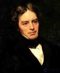
Fig. 8.1. Michael Faraday (1791–1867) — English physicist and chemist
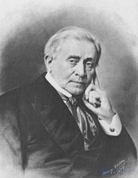
Fig. 8.2. J. Henry (1797–1878) — American physicist
Let us become acquainted with the experiments conducted by Faraday (Fig. 8.3, 8.4).
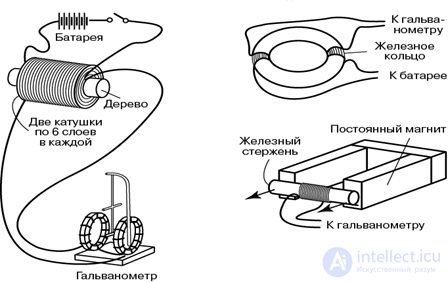
Fig. 8.3. Faraday's experiments
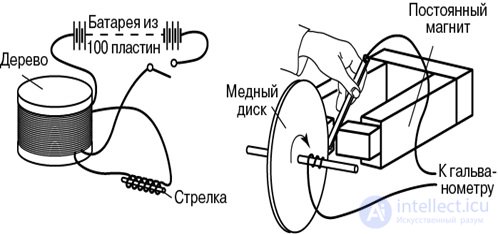
Fig. 8.4. Faraday's experiments
To become more closely acquainted with the phenomenon of electromagnetic induction, let us examine two experiments in detail (Fig. 8.5).
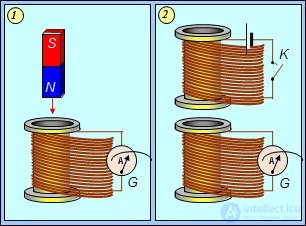
Fig. 8.5. An induced emf arises in the coil when:
1 — a permanent magnet approaches it; 2 — the current in the neighboring coil changes
The figure on the left shows a coil connected to a galvanometer G. If a permanent magnet is brought close to the loop, the galvanometer's needle deflects: a current flows through the coil. If the magnet is stationary, nothing happens. In the figure on the right, another coil is placed near a similar coil with a galvanometer. If the switch K is closed, an electric current flows through the upper coil. At that moment the galvanometer's needle deflects, registering a current pulse in the lower coil. The same thing happens when the switch K is opened.
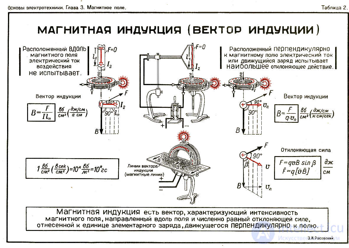
see Helmholtz coils.
In both cases, the loop with the galvanometer was not connected to a current source. Nevertheless, a current appeared in it, which indicates the emergence of some electromotive force. It is called the emf of electromagnetic induction. The experiments examined lead to the conclusion that an induced emf arises whenever something changes in a system of conductors.
Let us turn to one of the possible kinds of change in the system — the displacement of one of its conductors. Since a force acts on a current-carrying conductor, work will be done when this conductor is displaced. Let us consider the arrangement shown in Fig. 8.6.
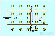
Fig. 8.6. Work done in moving a current-carrying conductor in a magnetic field
Regarding Fig. 8.6: the appearance of an induced current when a small section of a closed conducting loop moves in a magnetic field.
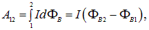
Let a segment of a current-carrying conductor  of length
  move from position 1 to position 2 under the action of the Ampere force in a magnetic field
|
|
(8.1) |
The work done by the field in moving the conductor a distance  is equal to
|
|
(8.2) |
The product  is the element of area swept out by the segment of conductor during its motion from position 1 to position 2. Thus,
|
|
(8.3) |
where  is the change in the flux of the magnetic flux density vector through the area enclosed by the current.
According to (8.3), the work done by the magnetic field when a movable current-carrying conductor is displaced within it is equal to the product of the current I in the conductor and the flux  through the surface swept out by the conductor during its motion.
The result obtained can be given a somewhat different interpretation. The currents flowing in a conductor are, one way or another, closed, forming a loop. If a current loop is displaced or deformed in an external magnetic field, the total work is determined by summing (integrating) the elementary amounts of work
|
|
(8.4) |
where  and
and  are the values of the magnetic flux in the initial and final states of the current loop (we assumed that the current in the loop does not change in this process).
Example 1. A current of 100 A flows through a ring of radius 10 cm made of thin flexible wire. A uniform external magnetic field of 0.1 T is created perpendicular to the plane of the ring. The direction of this field coincides with the direction of the ring current's own magnetic field on its axis. Determine the work A of external forces that must be expended to turn the ring into a square, without changing its orientation relative to the external field. Neglect the work done against elastic forces. The current in the ring is maintained constant. How does the result change if the external field has the opposite direction?
Solution. Method 1. The area of the ring is  , so the magnetic flux through the ring is
  . When the ring is deformed into a square, its perimeter does not change, so the side of the square is four times shorter than the circumference of the ring
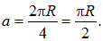
Its area is equal to

and the magnetic flux
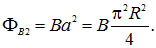
Therefore the magnitude of the work is equal to

Substituting the numerical values, we obtain

The work turns out to be negative, that is, it must be done against the forces of the field. Indeed, with a right-handed (as given) arrangement of the current and the external field, the Ampere force tends to stretch the ring — to increase its area. By turning the ring into a square, we decrease the area, thereby doing work against the forces of the field.
If the field has the opposite sign, then this work will be done by the Ampere force, and it will be positive. In solving the problem in this case, the flux of the external field is negative (the external field has reversed its direction, while the normal to the surface bounded by the loop remains the same, related to the direction of the current in the loop by the right-hand-screw rule). Therefore

and for the work 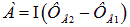 we get the same expression, but with the opposite sign.
Solution. Method 2. As is known, the magnetic moment of a current loop is equal to  , and its potential energy in a magnetic field is given by the expression

With a right-handed arrangement of the current and the magnetic field, the angle between the vectors Pm and B is zero, so that

The difference in potential energies upon deformation of the loop is equal to

Since  , the potential energy increased upon deformation, which requires that work be expended against the forces of the field. When the direction of the field is reversed, the angle between it and the magnetic moment is equal to
  , so that

and
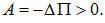
Naturally, we obtained the same results as with the first method of solution.
Example 2. A circular loop carrying a current of 20 A settles freely in a uniform magnetic field with a magnetic flux density of 0.016 T. The radius of the loop is 5 cm. Determine the work that must be done to turn the loop through the angles  ,
,  ,
,  about an axis coinciding with the diameter of the loop.
Solution. Since in the initial position the loop settled freely, its magnetic moment is parallel to the vector B. The flux through the plane of the loop is positive and equal to  . When the loop is turned through the angle
  , the flux becomes equal to
  . The work done in this process is equal to

From this we find



At the angles of rotation  , the work is negative: the loop is in a state of stable equilibrium, and effort must be expended against the forces of the field to move it out of the equilibrium state. But at
  the loop is already tending toward the equilibrium position on its own, so the work is done by the forces of the field, and this partially compensates for the work expended earlier. Over a full revolution
  , the work done by the forces of the field is exactly equal to the work done by external forces, so the total work turns out to be equal to zero.
This example can also be solved in another way — in terms of the potential energy of interaction of the magnetic moment with the field.
Let us note that using the magnetic moment of a current loop to calculate the work is possible only when the external field is uniform or weakly nonuniform. The latter means that the external field varies so little within the loop that this variation can be neglected. If the external field varies substantially within the loop, the exact result for the work can be obtained only by integrating the work of the Ampere force, taking into account the magnitude and direction of the external field at the point where it is applied. This approach is precisely what leads to the exact formula (8.4), obtained above using the example of a system with the simplest geometry, shown in Fig. 8.2. Thus, formula (8.4) is exact and general — for a problem of any geometry.
Let us now apply the law of conservation of energy to the system considered. Let  be the change in magnetic flux upon a small displacement of the conductor over time
  . The work done is equal to
  . At the expense of what source is this work done? Nothing has changed in the surrounding space. The only available energy is drawn from the current source. If its emf is equal to
  then over time
  the source will expend energy
  . This energy is spent on the release of heat in the resistance R and on the work of moving the conductor
|
|
(8.5) |
Dividing both sides by  and moving the term with the flux to the left-hand side of the equality, we obtain
|
|
(8.6) |
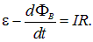
It is not hard to recognize Ohm's law in this equation: the right-hand side contains the voltage drop across the resistance, while the left-hand side should contain the sum of all the emfs acting in the circuit. The equation can therefore be rewritten in the form
|
|
(8.7) |
where
|
|
(8.8) |
This relation is the mathematical statement of Faraday's law of electromagnetic induction (Fig. 8.7).
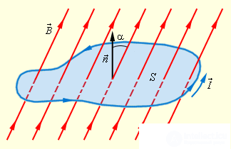
Fig. 8.7. Magnetic flux through a closed loop
What, then, is the physical reason for the appearance of an induced emf in this case? Let us consider almost the same system, but without a current source and without a closed circuit. Let a segment of conductor of length l move with velocity v perpendicular to the magnetic flux density vector B (Fig. 8.8).
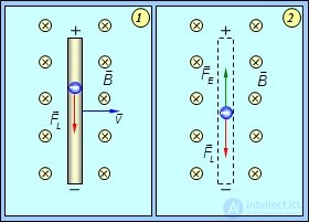
Fig. 8.8. Appearance, at the ends of a conductor moving in a magnetic field,
of a potential difference equal to the emf of electromagnetic induction
The magnetic field is uniform and the magnetic flux density lines  are perpendicular to the drawing and directed away from us. The free electrons in the conductor are acted on by the Lorentz force (whose direction is determined by the right-hand screw rule)
|
|
(8.9) |
where e — charge of the electron. Under the influence of the Lorentz force, a displacement of charges will occur and a certain potential difference  will arise at the ends of the conductor. The resulting electric field E will oppose the further displacement of charges, and their further motion will stop when the force exerted by the induced electric field
  becomes equal in magnitude, but opposite in direction, to the Lorentz force
  .
.
Thus, we obtain

from which
|
|
(8.10) |
Since  , then
|
|
(8.11) |
The speed of the conductor is equal to  , and the product
  is the area of the surface swept out by the conductor in time
  . We obtain, consequently,
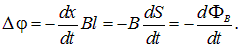
|
|
(8.12) |
We have arrived at the same result, since the potential difference at the ends of an open conductor is equal to the induced emf. (Recall that for an ordinary current source, too, the potential difference at its terminals with an open circuit is equal to the emf.) Since the Lorentz force acting on the negatively charged electrons is directed downward in Fig. 8.3, an excess of negative charge accumulates at the lower end of the conductor, and of positive charge at the upper end. Consequently, the potential of the upper end is higher than the potential of the lower end. We shall, however, discuss the sign of the induced emf separately.
Recall that earlier we considered an example (Sec. 6.7) concerning an airplane flying in a vertical magnetic field. It is easy to see that the problem in that example is identical to the problem of the motion of a conductor just considered. And from the Lorentz transformations we obtained then exactly the same results as now: compare formulas (8.10) and (6.43). Thus, both the law of conservation of energy and the equation of motion of a charge in a magnetic field, and even the relativistic Lorentz transformations for the electromagnetic field, all lead to the same law of Faraday — in physics (as, indeed, in the world in general) everything is interconnected.
Expression (8.8) for the emf of electromagnetic induction has a very general form: it does not include any specific characteristics of the motion — the speed of the conductor, its length, and so on. Everything is determined solely by the rate of change of the flux of the magnetic flux density vector. Moreover, it is completely unimportant by what means we change this flux. One can deform the loop, move it, or simply increase the magnetic flux density (Figs. 8.9, 8.10, 8.11, 8.12, 8.13). It is precisely the last option that was realized in the experiments we discussed at the beginning of this chapter. The mechanism by which the induced emf arises can differ, but the final result will be described by the same equation (8.8), which bears the name Faraday's law.
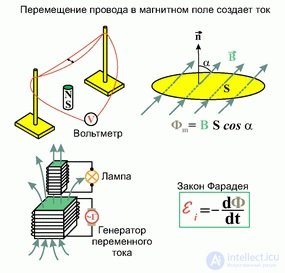
Fig. 8.9. Faraday's law
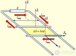
Fig. 8.10. Appearance of a current in a loop when a wire is moved in a constant magnetic field
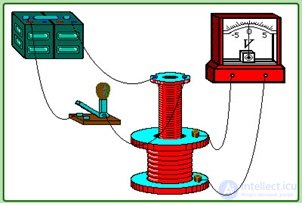
Fig. 8.11. Appearance of a current in a loop when a battery is connected
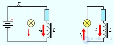
Fig. 8.12. Bright flash of a light bulb when the switch is opened
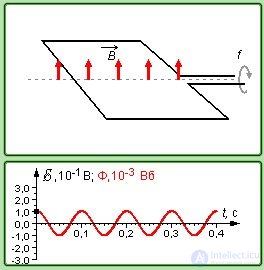
Fig. 8.13. Appearance of an alternating current upon rotation of a loop
Example 1. In a uniform magnetic field with a flux density of 0.4 T, a rod of length 10 cm rotates in a plane perpendicular to the field's flux density lines. The axis of rotation passes through one of the ends of the rod. Determine the potential difference U at the ends of the rod at a rotation frequency of 16  .
.
Solution. In time  the rod turns through an angle
  and sweeps out a sector of area
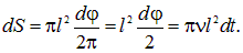
The potential difference is equal to the rate of change of the magnetic flux

Faraday's law applies not only to an individual loop or turn, but also to a coil, which can be regarded as N turns connected in series. In this case the total emf will be N times greater than the emf of a single turn, that is
|
|
(8.13) |
where the quantity
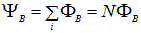
is called the flux linkage or total magnetic flux ( is measured in the same units as
  , that is, in webers).
Example 2. The magnetic flux density of the field between the poles of a generator's magnet is equal to 0.8 T. The rotor has 100 turns of area 400 cm2. Determine the rotation frequency of the armature if the maximum induced emf is equal to  = 200 V (Fig. 8.14).
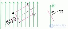
Fig. 8.14. Rotation of a loop in a constant magnetic field
Solution. The angle between the magnetic field and the normal to the plane of the turns changes according to the law  . The total magnetic flux through the rotor winding at time t is equal to
  . Differentiating the magnetic flux with respect to time, we obtain

The maximum value of the sine equals unity, hence the maximum value of the induced emf is equal to
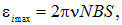
whence

An induced emf arises not only when a closed loop moves in a magnetic field or a magnet moves relative to a stationary loop. Suppose there are two coils with a common iron core serving as a magnetic circuit (Fig. 8.15).
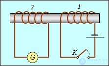
Fig. 8.15. An iron core as a magnetic circuit between two coils
With the circuit open, the magnetic flux in the system is zero. When switch K is closed, a current flows through coil 1, creating a magnetic field so that coil 2 is threaded by magnetic flux  . Therefore, when the switch is closed, over the time
  it takes the current to rise to its steady-state value, the flux through coil 2 changes by an amount
  . Correspondingly, an emf arises in it
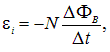
where N — the number of turns in coil 2, and an induced current flows, which will be registered by the galvanometer G.
When the growth of the current in coil 1 stops, the magnetic flux density becomes constant and the emf becomes zero. The current in coil 2 also stops flowing, and the galvanometer needle returns to its initial position. The same picture is observed when the circuit of coil 1 is opened, except that the galvanometer needle deflects in the opposite direction, which indicates a change in the direction of the current in coil 2.
If an alternating current is passed through coil 1, an alternating current of the same frequency will flow through the circuit of coil 2. This principle is widely used in transformer engineering.
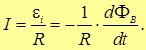
Let a loop have resistance R and let the magnetic flux through it change according to some law. The electromagnetic induction emf arising in the loop

drives a current in the loop
|
|
(8.14) |
The charge  , that has flowed in the loop over the time
  , is related to the current
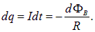
Integrating, we obtain for the charge Q that has flowed through the loop when the flux changes the following expression
|
|
(8.15) |
(we use the magnitude of the flux change, since the direction of the charge flow is not important to us here). From this, incidentally, follows the connection between the unit of magnetic flux and the units of charge and resistance

Example 3. A wire ring of radius 10 cm lies on a table. What charge will flow through the ring if it is turned from one side to the other? The resistance of the ring is 3 Ω. The vertical component of the induction of the Earth's magnetic field is equal to 50 μT.
Solution. The initial magnetic flux density through the ring is equal to  . After the ring is turned over, the magnitude of the flux remains the same, but the field lines now enter from the other side of the ring:
  . The required charge is equal to

In 1833, E.Kh. Lenz (Fig. 8.16) formulated a rule (Lenz's rule):
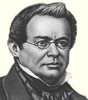
Fig. 8.16. E.Kh. Lenz (1804–1865) — Russian physicist
|
An induced current always has such a direction that its magnetic field counteracts the change in the magnetic flux threading the loop. |
Let us give an example of the application of Lenz's rule (Fig. 8.17, 8.18).
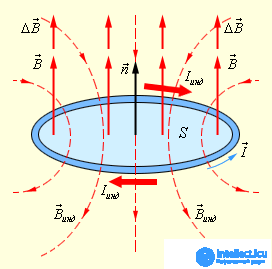
Fig. 8.17. Illustration of Lenz's rule
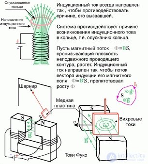
Fig. 8.18. Illustration of Lenz's rule
Looking at Fig. 8.8, we saw that excess positive charge accumulated at the upper end of the conductor. Consequently, during that short time while the motion of charges in the conductor had not yet ceased, the induced current flowed from bottom to top. By the right-hand (gimlet) rule (turning the handle from the direction of the current to the direction of the field), the Ampère force was directed to the left, opposing the motion of the conductor to the right.
In the experiment where a permanent magnet approaches a loop, the induced current also creates an opposing magnetic field (Fig. 8.19).
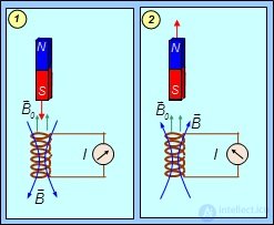
Fig. 8.19. When a permanent magnet is moved inside a coil, an induced current arises,
whose field opposes the motion of the magnet
Fig. 8.20 shows an experiment illustrating Lenz's rule. Two aluminum rings are mounted on the ends of a beam that can rotate about a vertical axis: one solid, the other — with a cut. When a permanent magnet approaches the first ring, it is repelled from it, and when it moves away — it is attracted, since the induced currents, in accordance with Lenz's rule, oppose the change in the magnetic flux enclosed by the ring. The magnet does not interact with the cut ring.
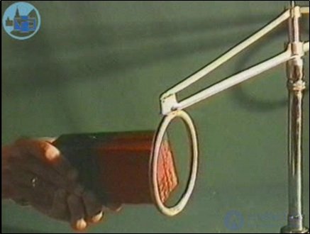
Fig. 8.20. Interaction of a permanent magnet with a conducting ring
Fig. 8.21 shows an experiment demonstrating the interaction of a conducting ring and an electromagnet. A ring placed on the end of a vertical core protruding from the winding flies upward when the current in the winding is switched on. With a horizontal arrangement of the core, in accordance with Lenz's rule, when the field is switched on the ring moves along the core away from the winding, and when it is switched off — back toward the winding.
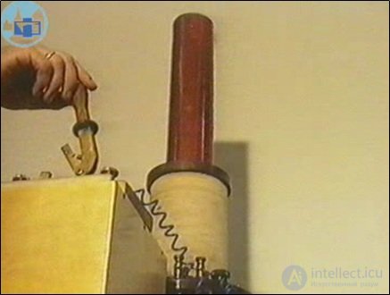
Fig. 8.21. Interaction of an electromagnet with a conducting ring
Mathematically, Lenz's rule is reflected by the minus sign in equation (8.8) of Faraday's law. Let us discuss this connection in more detail. Here difficulties can arise in determining the sign of the flux of the magnetic induction vector. When we dealt with closed surfaces in electrostatics, the positive direction was set by the outward normal. When an open surface is «stretched» over a loop with a current already flowing, the direction of the current sets the positive direction of the normal by the right-hand (gimlet) rule. We already became familiar with this when solving problems on finding the work done in deforming a loop. But what should be done in the case of using Faraday's law, when the surface is not closed and the direction of the current is not known to us and we only want to determine it?
Consider Fig. 8.22. It shows a loop threaded by field lines of an external magnetic field B.
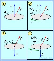
Fig. 8.22. Illustration of the application of Lenz's rule:
changing the direction of traversal of the loop does not change the sign of the induced emf in Faraday's law
Let us choose the positive direction of traversal of the loop counterclockwise (top row). In Fig. 8.22-1 the magnetic field is constant. With this choice of the positive direction of traversal of the loop and an acute angle between the normal n to the loop and the magnetic induction vector B, the magnetic flux through the loop is positive  . In Fig. 8.22-2 the magnetic field is increasing. The positive flux through the loop is also growing, and therefore
  It then follows from Faraday's law that the induced emf and, consequently, the induced current are negative. This means that the current flows in the direction opposite to the chosen path of traversal of the loop, that is, clockwise.
Let us now choose a different positive direction of traversal of the loop — clockwise (Fig. 8.22-3). The flux of the constant magnetic field is negative here (the angle between n and B is obtuse, and its cosine is negative). As the field increases, the absolute value of the flux grows, but since it is negative, then ( , as shown in Fig. 8.22-4). It then follows from Faraday's law that the emf and the induced current are positive. This means that the direction of the current coincides with the chosen direction of traversal of the loop, that is, the current flows clockwise.
We have shown that the direction of the induced current does not depend on the choice of the positive direction of traversal of the loop. This is how it should be, since the choice of the direction of traversal of the loop is made by us, and arbitrarily at that, while the direction of the current is a physical reality that cannot depend on our arbitrary choice. We encountered a similar situation when studying Kirchhoff's rules.
Induced currents arise not only in wire loops, but also within the bulk of massive conductors. In this case they are called eddy currents or Foucault currents. Because of the low resistance of the conductors, they can reach large magnitudes. By Lenz's rule, eddy currents also act against the cause that produces them. This underlies the idea of electromagnetic dampers that calm the oscillating parts of instruments (galvanometer needles, etc.). A metal strip is mounted on the moving part of the instrument, located in the field of a strong magnet. When the system moves, J. Foucault currents (Fig. 8.23) brake it, but they are absent when the needle is at rest and do not prevent it from stopping at the required place, according to the value of the quantity being measured (unlike friction forces).
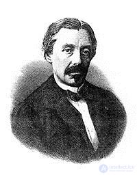
Fig. 8.23. Léon Foucault (1819–1868) — French physicist and astronomer
The result of the reasoning presented can be summarized as the following formulation of Lenz's rule: an induced current is always directed so as to oppose the cause that produced it. Regardless of what that cause is.
For example, if a wire ring falls in a nonuniform magnetic field under the action of gravity, an induced current flows in it. Correspondingly, an Ampère force acts on the ring. Without calculating anything, one can be certain that this Ampère force will be directed upward, so as to — according to Lenz's rule — oppose gravity, which is the cause of the ring's fall, which entails a change in the magnetic flux, and this leads to the appearance of an induced current, on which an Ampère force acts, slowing the fall…
Below we consider experiments in which the properties of Foucault currents are studied.
Fig. 8.24 shows an experiment demonstrating the fall of bodies in a nonuniform magnetic field. A nonuniform magnetic field slows the motion of conducting objects because of Foucault currents that arise in the conductors when the magnetic flux through them changes. It demonstrates the unimpeded fall of a dielectric wooden disk between the poles of a strong electromagnet and the slow fall of copper and aluminum disks in the magnetic field, reminiscent of the motion of bodies in a medium of high viscosity.
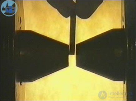
Fig. 8.24. Fall of bodies in a nonuniform magnetic field
When a strong permanent magnet falls inside a vertical conducting tube, Foucault currents arise in its walls, slowing this fall. The experiment (Fig. 8.25) demonstrates the free fall of a nonmagnetic aluminum cylinder in different tubes, as well as of a small magnet in a glass tube. It then shows the slowing of the fall of this magnet in an aluminum tube and its very slow fall in a thick-walled copper tube.
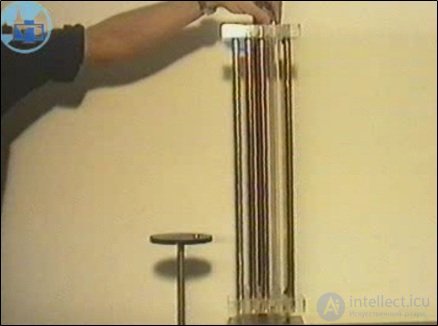
Fig. 8.25. Fall of a magnet in tubes
Fig. 8.26 shows damping of pendulum oscillations. A thick solid copper plate, attached to the end of a physical pendulum, moves during its oscillations between the poles of a strong electromagnet. Weakly damped oscillations of the pendulum, after the magnetic field is switched on, begin to damp rapidly, becoming practically aperiodic oscillations. If a copper plate cut in the shape of a comb is attached to the end of the pendulum, the strong damping of the pendulum's oscillations disappears, since Foucault currents can no longer close within the volume of the conductor.
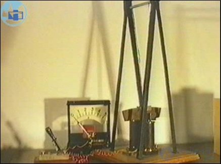
Fig. 8.26. Damping of pendulum oscillations
The experiment in Fig. 8.27 shows the levitation of a solid conducting ring. Foucault currents can arise not only in conductors when they move in a nonuniform magnetic field, but also when this field changes rapidly. A solid aluminum ring, placed on the vertical core of an electromagnet fed by an alternating current with a frequency of 50 Hz, hangs in the air, while an identical but cut ring falls freely onto the winding.
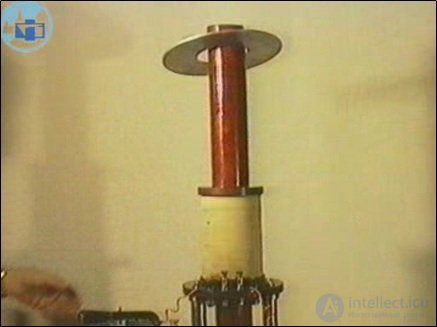
Fig. 8.27. Levitation of a solid conducting ring
Fig. 8.28 shows the interaction of a conductor and an electromagnet. A thick copper disk is mounted in bearings on an axle with a handle. An electromagnet is mounted nearby on the same axle. If the switched-on electromagnet is rotated by the handle, the disk begins to rotate in the same direction. If, conversely, the disk is rotated by the handle near the electromagnet, the latter also begins to rotate. The forces of interaction between the disk and the electromagnet, similar in character to viscous friction forces, are due to the appearance of Foucault currents in the disk.
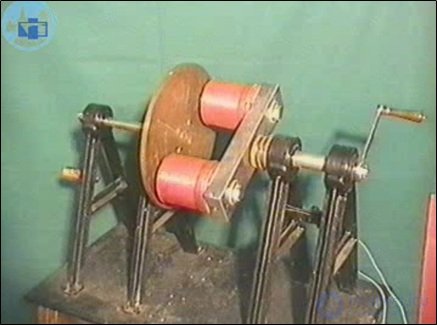
Fig. 8.28. Interaction of a conductor and an electromagnet
When a superconductor moves in a magnetic field, the undamped Foucault currents that arise in it do not allow the external field to penetrate inside it. The result is a kind of mirror image of the magnet, repelling it from the superconductor. Fig. 8.29 demonstrates the levitation of a small magnet above a large disk of high-temperature superconductor (HTSC ceramic), cooled to the temperature of liquid nitrogen (77 K), that is, below the critical temperature of the transition of HTSC ceramic to the superconducting state.
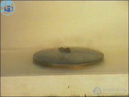
Fig. 8.29. Levitation of a small magnet above a large disk of high-temperature superconductor (HTSC ceramic)
The thermal effect of Foucault currents is used in induction furnaces for melting metal or cooking food. Such a furnace is, in essence, a large coil fed by a high-frequency current of large magnitude. The coil creates an alternating magnetic flux through the sample placed in the furnace, and the resulting Foucault currents heat the latter.
Fig. 8.30 demonstrates the thermal effect of Foucault currents. An aluminum ring is placed on the core of an electromagnet fed by an alternating current with a frequency of 50 Hz, and held for some time with pliers in the alternating magnetic field. The ring is then lowered into water, and it boils, showing that the ring has been heated by induced currents to a high temperature.
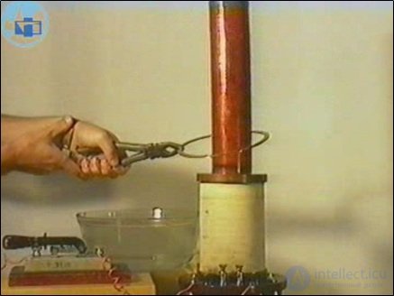
Fig. 8.30. Thermal effect of Foucault currents
Let us again consider a loop with a current, but this time we will not place it in an external magnetic field. The current itself creates its own field B, which threads the loop. This field, as follows from the Biot — Savart — Laplace law, is proportional to the current

The loop's own magnetic field gives rise to a magnetic flux Y through the surface bounded by this loop, which will also be proportional to the current in the loop

Let us introduce a proportionality coefficient L
|
|
(8.16) |
The proportionality coefficient L is called the inductance of the loop.
|
The inductance of a loop is numerically equal to the magnetic flux of its own magnetic field through the surface bounded by the loop, provided a unit current flows in the loop. |
The inductance of a loop is determined by the shape and dimensions of the loop, as well as by the properties of the surrounding medium.
|
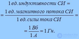
In the SI system the unit of inductance is the henry (H)
|
If an alternating electric current flows in a conducting loop, then the magnetic field of this current also changes with time. The loop's own magnetic flux, created by this field, is also variable. A change in the magnetic flux entails the appearance of an electromagnetic induction emf.
|
The phenomenon of the appearance of an induced emf in a closed conducting loop as a result of a change in the current flowing in this loop is called the phenomenon of self-induction. |

The emf that arises in this case is called the self-induction emf. The phenomenon of self-induction is a particular case of electromagnetic induction.
The phenomenon of self-induction is, in particular, the cause of a phenomenon called «extra currents of closing and opening». It consists in the following. The self magnetic field in a direct-current circuit changes at the moments the circuit is closed or opened. This means that at such moments a self-induction emf must arise in the circuit. The direction of the self-induction currents follows from Lenz's rule. When the circuit is closed, the self-induction emf causes a current that opposes the increase of the main current in the circuit, which makes the rate of growth of the current finite, while when the circuit is opened, the self-induction current, opposing its decrease, makes the rate of decay of the current finite. If it were not for the self-induction emf, when the circuit is closed the current would instantaneously rise to its steady-state value, and when the circuit is opened, it would instantaneously fall to zero.
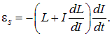
Let us derive the formula for the self-induction emf  . For this we need to differentiate the total magnetic flux enclosed by the conducting loop with respect to time
|
|
(8.17) |
If the loop does not change its shape, and there are no ferromagnets near the loop, then its inductance does not depend on time. However, even with the shape of the loop unchanged, in the presence of ferromagnets, for example a ferromagnetic core, the inductance of the loop depends on the current in it and, thereby, on time, if the current is alternating. Thus, in the presence of ferromagnets
 ,
,
which must be taken into account when differentiating
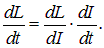
Substituting this expression into (8.17), we obtain for a stationary loop in a medium
|
|
(8.18) |
If, however, the inductance of the loop does not depend on the current in it, then we have
|
|
(8.19) |
We arrive at the law of self-induction. In this simplest case:
|
In the absence of ferromagnets, the self-induction emf in a circuit is directly proportional to the rate of change of the current in that circuit. |
Let us consider the coil to be long, and the magnetic field inside it — uniform. Let us pass a current I through the solenoid. Then the magnetic induction inside the solenoid is equal, as we know (see (6.20)), to

where  — the permeability of the core, and n — the number of turns per unit length. The total number of turns in the coil is equal to
  , where l — its length. Let S — be the cross-sectional area of the solenoid. The total magnetic flux (flux linkage) is defined as
|
|
(8.20) |
where V — the volume of the solenoid: V = Sl. According to the definition of inductance as the proportionality coefficient between  and I, we obtain the value of the inductance of a long solenoid (Fig. 8.31)
|
|
(8.21) |
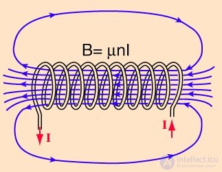
Fig. 8.31. Inductance of a solenoid
When a circuit is closed or opened (that is, in cases when the current in the circuit changes in magnitude), additional currents arise in it owing to the phenomenon of self-induction, which by Lenz's rule are always directed so as to oppose the cause that produces them, that is, to oppose the growth or decay of the current in the circuit. Consequently, as already stated, when the circuit is closed the self-induction emf will slow the rate of growth of the current, and when it is opened, on the contrary, slow the rate of decrease of the current in it.
Let us consider a circuit consisting of a resistance, an inductance, and a current source (Fig. 8.32).
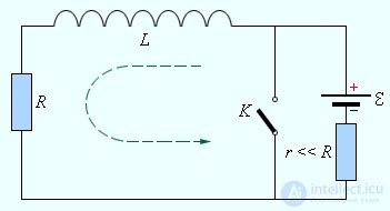
Fig. 8.32. A circuit containing a coil, a resistance, and a direct-current source
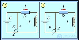
Fig. 8.33. Currents of closing (1) and opening (2) of a circuit with inductance
Let us assume that the internal resistance of the source and the resistance of the coil, connected in series with it, are already included in the resistance R. After the extra currents of closing and opening have disappeared and a steady current is established, the current in the circuits shown in Fig. 8.33, according to Ohm's law, will be equal to

With the switch open, no current flows. What happens if the switch is closed, moving it from position 1 to position 2?
Let us denote by I the instantaneous value of the current in the circuit:  (a function of time). If we take into account the self-induction emf, then at each instant of time Ohm's law still holds
|
|
(8.22) |
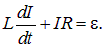
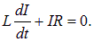
Let us substitute expression (8.19) into (8.22), assuming that the inductance does not depend on the current. As a result of applying Ohm's law we obtain a differential equation for the current in the circuit
|
|
(8.23) |
This equation is easily integrated
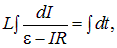
or
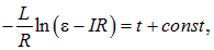
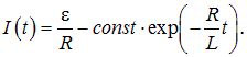
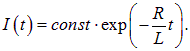
whence follows the general solution of equation (8.23)
|
|
(8.24) |
We determine the integration constant const from the initial condition: at time t = 0 (the switch is closed) there was as yet no current in the circuit, that is, I(0) = 0. Then

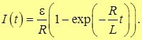
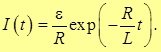
Thus, the time dependence of the closing current in a circuit with inductance has the form
|
|
(8.25) |
The quantity

has the dimension of time and is the characteristic time of current growth in a circuit with inductance. At first the current grows linearly from a zero value, then the rate of its growth begins to decrease and the current asymptotically approaches its limiting value

equal to the current in this same circuit in the absence of inductance. In practice, given the actual accuracy of current measurements, the limiting value of the current is reached in times approximately equal to  (Fig. 8.34).
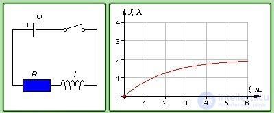
Fig. 8.34. Closing current of a circuit with inductance
Let us now consider Fig. 8.33-2. Initially the switch was in position 1, and a current flowed in the circuit

When the switch is moved to position 2, the current source is disconnected from the circuit, and the current I begins to decrease. Ohm's law for the closed section of the circuit now takes the form
|
|
(8.26) |
Unlike (8.23), in the open circuit there is no longer an emf  and only the self-induction emf acts. Equation (8.26) is integrated even more easily
|
|
(8.27) |
Taking into account that the initial current in the circuit was equal to
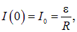
for the time dependence of the opening current in a circuit with inductance we obtain
|
|
(8.28) |
Fig. 8.35 shows an experiment illustrating the phenomena that occur when a circuit containing inductance is closed and opened. An electric lamp is included in the power circuit of a large inductance coil. When the circuit is closed with the switch, the lamp does not light up immediately, since the self-induction emf opposes the change in the current (E.Kh. Lenz's rule). When the circuit is opened, a bright flash is observed, because the source of current becomes the self-induction emf of the coil, which, upon an abrupt change in the current, is usually noticeably greater than the emf of the source.
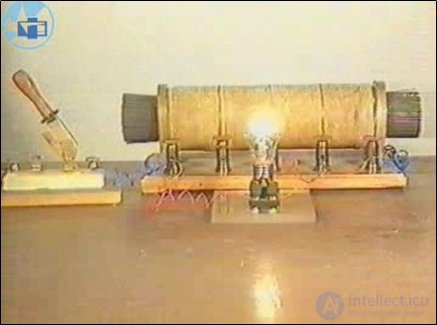
Fig. 8.35. Phenomena occurring when a circuit containing inductance is closed and opened
Example. A coil with an inductance of 0.5 H and a resistance of 8 Ω is connected to a source with an internal resistance of 2 Ω. Find the time T during which, after the circuit is closed, the current in the coil reaches a value differing from the maximum by  .
.
Solution. In this problem the total resistance of the circuit is equal to

where r — the internal resistance of the source, and  — the resistance of the coil. According to (8.25), the current at time T is equal to
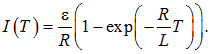
By the condition of the problem,

whence

Let us return again to the process of closing the circuit in Fig. 8.33-1. Multiplying the right and left sides of equation (8.23) by  , we obtain
|
|
(8.29) |
The left side of equation (8.29) expresses the work done by the current source over time  . On the right side, the first term is the amount of work spent on releasing Joule heat in the conductor. It is clear that before us is the equation of the law of conservation of energy in the circuit under consideration. What, then, is the meaning of the second term? It is associated with the coil, as evidenced by the factor L, and represents the work expended in overcoming the opposition of the self-induction emf. Where does this work go? In the process of closing the circuit,
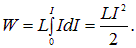
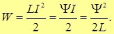
 a magnetic field is created by the coil. This means that the work in question is accumulated precisely in the coil, as the energy of its magnetic field stored in it. The current grows from zero to some steady-state value I. Therefore the total energy of the coil's field is equal to
|
|
(8.30) |
Since

this same result can be written in the forms
|
|
(8.31) |
These formulas are very similar to the expressions for the energy of a capacitor as a function of its charge or the potential difference across its plates. We recall that they can be brought to a form in which the volume of the capacitor is explicitly isolated. This allowed us to relate the energy density of the electric field to its strength. Let us carry out an analogous program for the magnetic field as well, using as the «coil» a sufficiently long solenoid.
The inductance of the solenoid is given by expression (8.21)
The magnetic induction in the solenoid is determined by formula (7.18)

Let us express the density of the number of turns in the solenoid in terms of the magnetic field in it

and substitute it into the expression for the inductance of the solenoid. We obtain
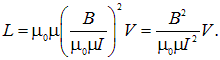
Finally, let us substitute this expression into formula (17.28) for the energy of the field in the coil
|
|
(8.32) |
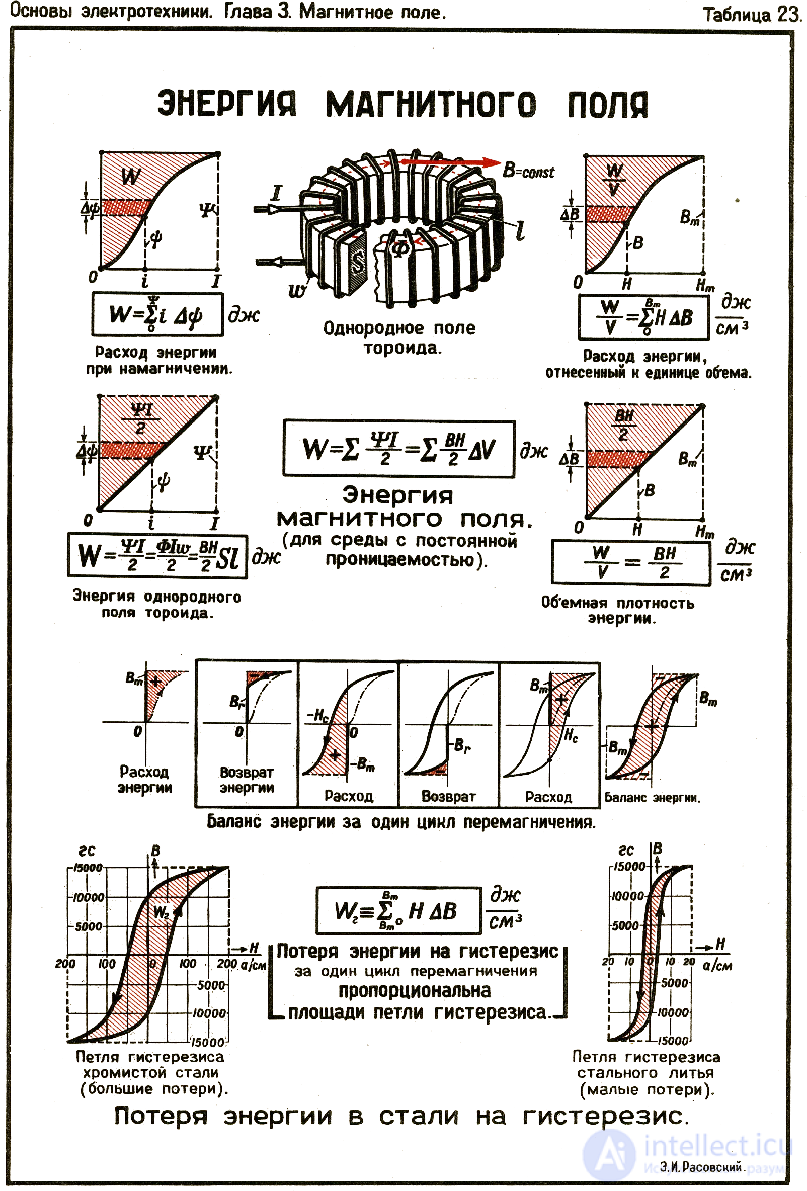
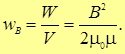
We have achieved our goal: the parameters of the solenoid, with which we started, are not present in this formula. We have expressed everything in terms of the magnetic induction of the field, and the energy in the coil turns out to be proportional to its volume. From this follows the expression for the energy density of the magnetic field (regardless of by what and how it was created)
|
|
(8.33) |
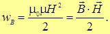
Recalling the relation between the magnetic field strength and the magnetic induction

we find equivalent representations for the energy density of the magnetic field:
|
|
(8.34) |
For a magnetic field in vacuum, one should set  in all these formulas. It is easy to notice the similarity of (8.34) with the analogous formulas (3.35), (3.36) for the electric field (Fig. 8.36, Fig. 8.37).
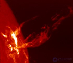
Fig. 8.36. The powerful magnetic field of the Sun produces plasma ejections
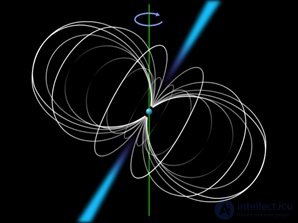
Fig. 8.37. The powerful magnetic field of a neutron star
Example. Compare the energies contained in a volume of 1 L, if it is permeated by: 1) a uniform electric field with strength E = 100 kV/m; 2) a uniform magnetic field with induction B = 1 T.
Solution. The energy of the electric field is equal to
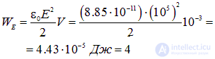
The energy of the magnetic field is equal to

Both of these fields are considered sufficiently strong, but can be created without particular difficulty. The problem demonstrates that it is practically more advantageous to store energy in a magnetic field: in this example the ratio of the energies is equal to

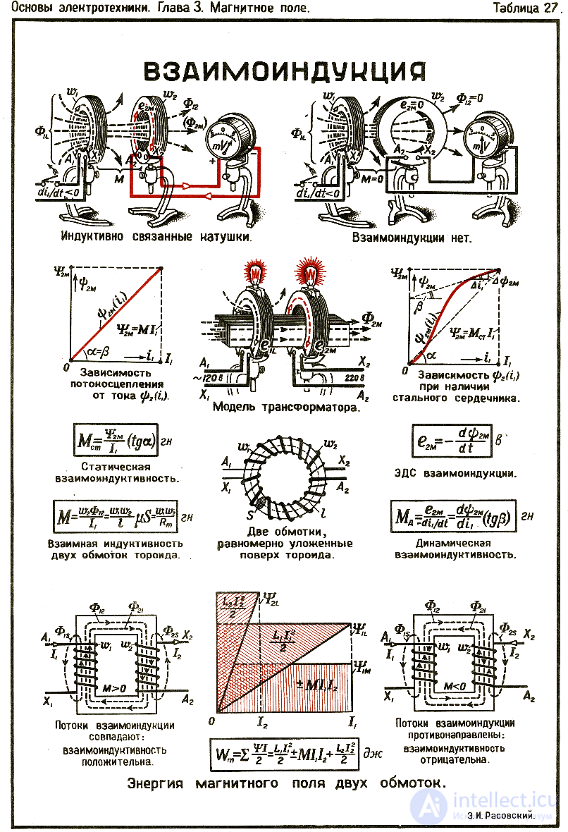
Mutual induction (mutual inductance) — the phenomenon of an induced emf arising in one loop when the current in a second loop changes, and vice versa. Mutual induction — a particular case of electromagnetic induction .
When the current in the first loop changes, an emf arises in the second:
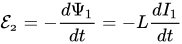
where
 — the electromotive force in the second loop,
 — the flux linkage of the first loop,
 — the current in the first loop,
 — the mutual inductance of the loops.
When the current in the second loop changes, an emf arises in the first:
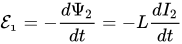
where
 — the electromotive force in the first loop,
 — the flux linkage of the second loop,
 — the current in the second loop,
— the mutual inductance of the loops.
The phenomenon of mutual induction is used to raise and lower the voltage of alternating current in transformers.
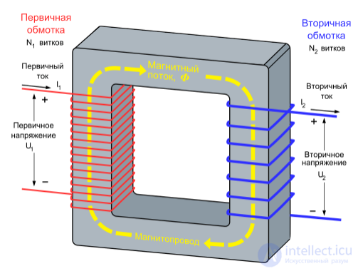
Appearance of an induced emf in the secondary winding of a transformer
Let us consider a system of wires carrying currents 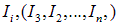 . The permeability of the medium is assumed to be an arbitrary function of the coordinates, but its dependence on the magnetic field H is neglected.
The flux of the magnetic induction vector  through a particular turn is the sum of the fluxes from each turn, proportional to the current in these turns
|
|
(8.35) |
The coefficient  , under the condition
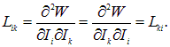
  , are called the coefficients of mutual induction. An important property of these coefficients is their symmetry:

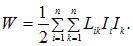
They depend only on the mutual arrangement of the loops. The Appendix proves the formula for the energy of the magnetic field
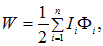
Substituting expression (8.35) here, we obtain
|
|
(8.36) |
From this the equality of the coefficients of mutual induction follows immediately. Indeed,
|
|
(8.37) |
Proving precisely this equality was the goal of this article. This involves the use of such concepts as the vector potential and Maxwell's equations. Interestingly, the same result can be obtained by another, even simpler route.
The phenomenon of mutual inductance leads to the formation of an induced current in one loop when the magnetic flux of another loop changes (Fig. 8.38, 8.39).
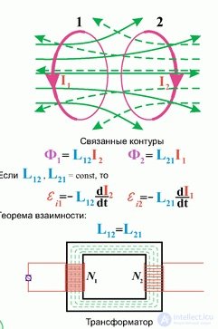
Fig. 8.38. Mutual induction
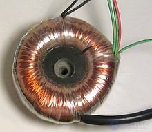
Fig. 8.39 Toroidal transformer
Let us consider two (infinitesimally) small stationary loops with currents I1 and I2 . By Newton's third law
|
|
(8.38) |
where, for example,  is the force acting on the second turn from the first.
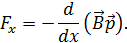
If we choose the x axis along the line connecting the loops, then for the force acting on the turn we have
|
|
(8.39) |
 — magnetic flux density at the location of the turn with magnetic moment
  .
.
In our case the following equality must hold
|
|
(8.40) |
as a consequence of equations (8.38) and (8.39). Here B1(2) — magnetic flux density in the region of turn 1(2), with an infinitesimally small area vector  , whose magnetic moment is
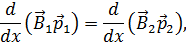
  . Together with equation (8.40), this means that
|
|
(8.41) |
up to an additive constant, which is obviously equal to zero. The flux of the magnetic flux density vector through an infinitesimally small loop is by definition  . Substituting this expression for turns 1 and 2 into (8.41), we have
|
|
(8.42) |
Furthermore, by the definition of the mutual inductance coefficients, we have
 .
.
Substituting these equalities into (8.42) leads to the required equality of the mutual inductance coefficients for small turns.
Further proof of the equality for current loops of arbitrary shape presents no difficulty. Indeed, any large loop can be broken up into many small ones, after which it is easy to obtain the same result for an arbitrary contour. Thus, the equality of the mutual inductance coefficients is a direct consequence of Newton's third law.
It is known that in the presence of ferromagnets rule (8) may not hold. Nevertheless, even in this case a similar equality can be satisfied. Let us illustrate equality (1) with a specific example of a toroidal core made of a ferromagnet. Let us consider a common situation where two loops with different numbers of turns are wound on the core. The magnetic field created by the currents flowing through both loops is practically entirely concentrated in the ferromagnet.
If a current  flows in loop «1», then in loop «2» the flux linkage is

Similarly, when a current  flows in loop «2», a magnetic flux (flux linkage) arises that passes through loop «1»

Here  and
and  — are the mutual inductance coefficients.
A current  flows through the first winding, which produces a magnetic field H1, whose magnitude is easily calculated from the circulation theorem

Here C — is a closed path of length l, passing inside the ferromagnet. The magnetic flux density flux passing through the cross-section of the core is easily found
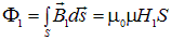
Consequently, the flux linkage through loop «2»:
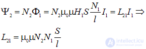
We have obtained an expression for the mutual inductance coefficients that is symmetric with respect to indices 1 and 2. Therefore, it is obvious that analogous reasoning for the second loop will lead to the same result and, hence, to the equality of the mutual inductance coefficients.
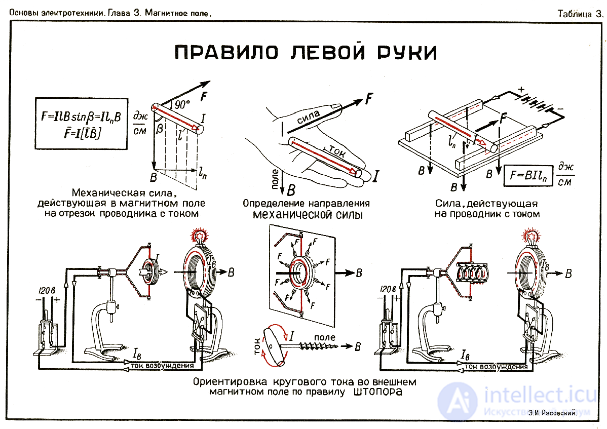
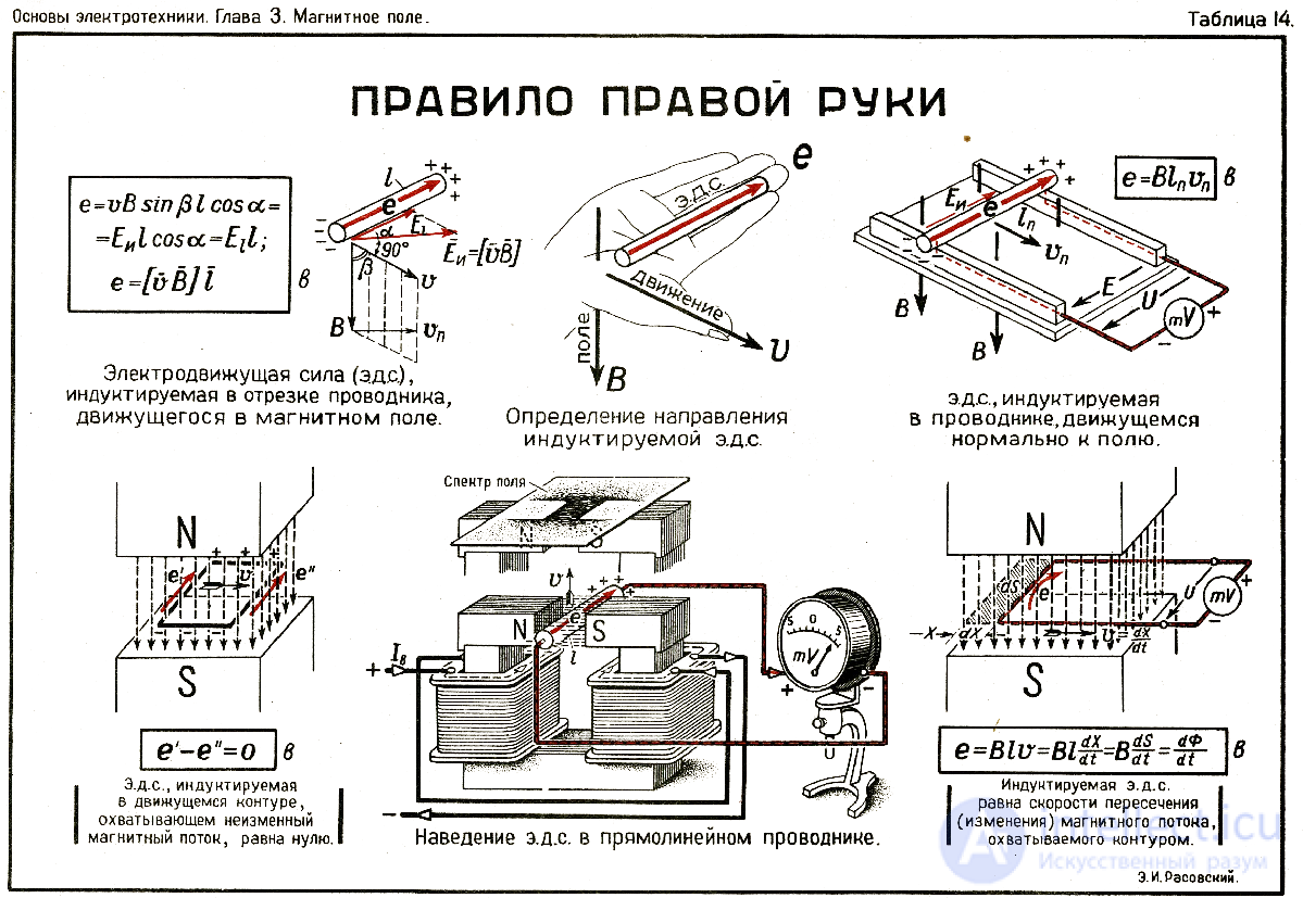
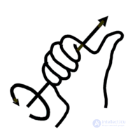
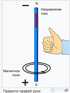
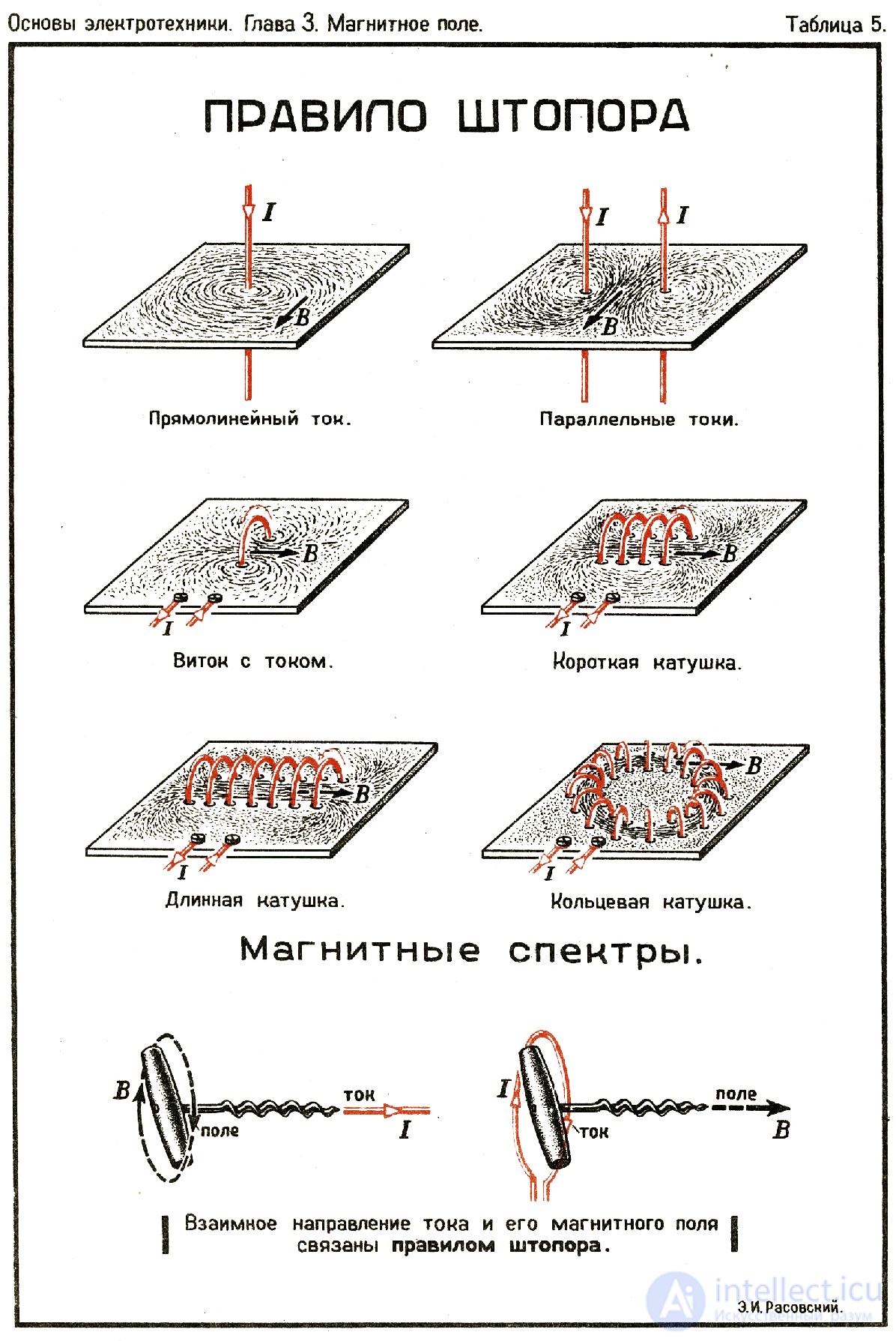
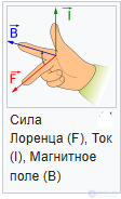
fig. right-hand rule, left-hand rule, corkscrew rule, gimlet rule
The corkscrew rule (screw rule) — is any of a number of variants of a mnemonic rule for determining the direction of a cross product and closely related to it, the choice of a right-handed basis in three-dimensional space, the convention of positive orientation of the basis in it, and, correspondingly — the sign of any axial vector defined through the orientation of the basis.
As a rule, the choice of one of the two possible directions of an axial vector is considered purely conventional; it only needs to be applied consistently, so that the sign does not end up mixed up in the final result of the calculations. This is exactly what the rules described in this article serve for: they allow one to always adhere to the same choice.
Left-hand rules
First left-hand rule
If the palm of the left hand is positioned so that the magnetic field induction lines enter the inner side of the palm, perpendicular[g] to it, and the four fingers point along the current, then the thumb, held out at 90°, will indicate the direction of the force acting on the current-carrying conductor from the magnetic field. This force is called the Ampere force.Second left-hand rule
If a charge is moving and the magnet is at rest, then the left-hand rule applies to determine the direction of the force: «If the left hand is positioned so that the magnetic field induction lines enter the inner side of the palm perpendicular to it, and the four fingers point along the current (along the motion of a positively charged particle or against the motion of a negatively charged one), then the thumb, held out at 90°, will show the direction of the acting Lorentz or Ampere force».
Magnetic field energy of a system of current loops
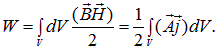
The magnetic field energy of a system of current loops requires knowledge of Stokes' theorem, the Ostrogradsky — Gauss formula and Maxwell's equations. On a first reading this can be skipped
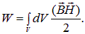
We use the known expression for the magnetic field energy
|
|
(A1) |
Here  and
and  — are the magnetic flux density and field strength, with
  . It is assumed that the permeability does not depend on
  , i.e., the medium is not ferromagnetic. Integration is carried out over the entire volume occupied by the magnetic field. We are interested in the energy of the whole system (of current loops), so the volume is assumed to be large enough that the magnetic field is absent on its surface. Let us express the scalar product in terms of the vector potential
  . Using the relation between the magnetic field and the vector potential,
  , as well as the basic formulas of vector analysis, we obtain:

When integrating over the entire volume, the second term vanishes. Indeed:
|
|
(A2) |
The last equality holds because the integration is carried out over the surface enclosing the entire region occupied by the magnetic field. As already mentioned, H = 0 on this surface. Next, let us use Maxwell's equation
|
|
(A3) |
which holds in the absence of electric fields. Substituting (A3), (A2) into (A1), we obtain
This is a general expression; in deriving it no assumptions were made about the shape of the conduction current density j. Suppose now that this current density is created by current loops Ii
Then  only in the regions occupied by thin wires. Choosing a linear element of the wire
  with cross-sectional area
  , we can write

Here it is taken into account that all three vectors are co-directed. Then, since this equality holds for all loops with their own
currents  , we obtain the expression for the energy of «n» current loops in the form

Integration is carried out over all volumes Vi, in which the current density is nonzero.
Using Stokes' theorem for the vector potential 


we obtain the final expression for the magnetic field energy
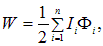
|
|
(A4) |
Here Fi — is the flux of the magnetic flux density vector through the surface bounded by the i-th current loop. It is created by the magnetic fields of all the current loops.
In the main text, the relation between the mutual inductance coefficients is derived on the basis of formula (A4).























Comments