Electric Voltage
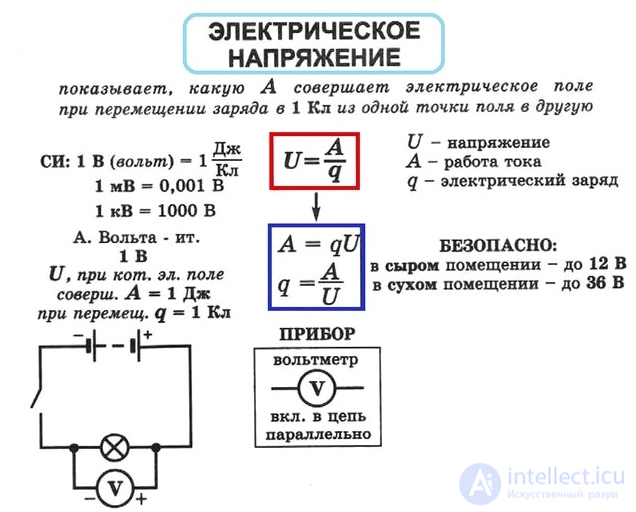
Electric voltage – a physical quantity characterizing the electric field that creates a current, equal to the ratio of the power of the current to its strength. The unit is 1 volt (1 V).
Let us recall that the purpose of any source of electrical energy is the long-term maintenance of unequal charges on its poles, so that an electric field exists between them (see § 8-g). Only this field can move charged particles in wires and loads, giving rise to an electric current of the power we need.
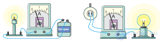
Let us turn to an experiment (see figure). A current of equal strength passes through both lamps: 0.4 A. But the larger lamp shines brighter, that is, it operates at greater power than the smaller one. It turns out that the power can differ even when the current strength is the same.
Besides the current strength, the power of the current in a conductor is also affected by a second physical quantity – the electric voltage. It is known that the voltage produced by a «battery» is less than the voltage produced by the mains supply. This means that the field between the poles of the battery, moving electrons through the wires and the lamp on the left, creates a current of lower power than the field between the contacts of the outlet, moving electrons through the wires and the lamp on the right. That is why the brightness of the lamps differs.
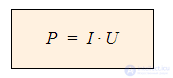
In physics, the dependence of electric power simultaneously on current strength and electric voltage is expressed as a product:
P – power of the electric current, W
I – strength of the electric current, A
U – electric voltage, V
Current power – a physical quantity characterizing the rate at which electrical energy is converted into its other forms. The unit of measurement is 1 watt (1 W).
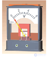
A voltmeter is used to measure electric voltage (see figure). It is always connected in parallel with the section of the circuit across which the voltage is being measured. The unit of electric voltage is 1 volt (1 V). This is the voltage which, at a current strength of 1 A, produces a current of power 1 W. Note: we will study the physical meaning of electric voltage in the next section.
Questions
- The ammeters in the experiment with the lamps show that ...
- The larger lamp gives off more heat and light, therefore ...
- From the experiment described, the following observation follows: ...
- To explain this, we assume that ...
- When we say that the voltages of the battery and of the mains differ, we mean: ...
- The fields in the left-hand and right-hand circuits create currents of different powers, ...
- The boxed formula with the product reflects ...
- In physics and engineering, voltmeters are used ...
- When taking a voltage measurement, a voltmeter ...
- A voltage of one volt is ...
Laws of voltage distribution in parallel and series connections
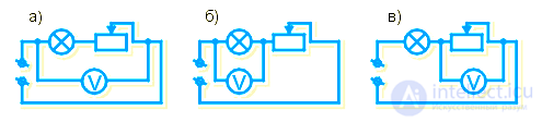
Let us now become acquainted with the laws of voltage distribution in circuits with various connections of conductors. Let us carry out some experiments.
In diagrams a-b-c, a lamp and a rheostat are connected in series. First the voltmeter is connected to the outer points of the connection between the lamp and the rheostat (diagram a), and the voltage is denoted by the symbol Utot. Then the voltmeter is connected only to the lamp (diagram b), and the voltage is denoted by the symbol U1. After that, the voltmeter is connected only to the rheostat (diagram c), and the voltage is denoted by the symbol U2.
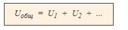
Repeated measurements in this and similar experiments show that in a circuit with a series connection of conductors, the voltage across the whole connection is equal to the sum of the voltages across the individual conductors:
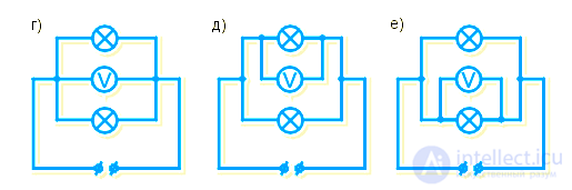
In diagrams d-e-f, two lamps are connected in parallel. First the voltmeter is connected to the outer points of the connection of the lamps (diagram a), and the voltage is denoted Utot. Then the voltmeter is connected to the first lamp (diagram b), and the voltage is denoted U1. After that, the voltmeter is connected to the second lamp (diagram c), and the voltage is denoted U2.
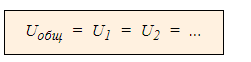
Repeated measurements in this and similar experiments show that in a circuit with a parallel connection of conductors, the voltage across each of the conductors is equal to the voltage across the whole connection:
Questions
- Different types of conductor connections are characterized by different ...
- In the top three diagrams, the loads ...
- The voltage on a voltmeter connected to the lamp and the rheostat ...
- The symbol U1 denotes the voltage when ...
- The symbol U2 denotes the voltage when ...
- The law for voltages in a series connection was obtained by carrying out ...
- The law Utot = U1 + U2 + ... means: ...
- In the bottom three diagrams, the loads ...
- The symbol Utot in the bottom diagrams denotes the voltage when ...
- The law Utot = U1 = U2 = ... means: ...
Interesting facts
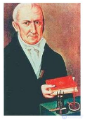
the unit of voltage, the volt, is named in honor of the Italian scientist A. Volta, who created the first long-lasting source of electrical energy – a battery of galvanic cells? This happened at the very beginning of the 19th century and became a powerful stimulus for the development of both science and electrical engineering – a new engineering discipline.
See also
See also


Comments