
Lecture
At the end of the 17th century, on the basis of centuries of experience and the development of ideas about light, Newton put forward the theory of the emission of light particles (corpuscles), which travel in straight lines and obey the laws of mechanics. According to this theory, the reflection of light was likened to the reflection of elastic balls upon striking a plane, which led to the law of geometrical optics known from the school curriculum: «the angle of incidence equals the angle of reflection». The law of refraction of light at the boundary between two media was explained by the attraction of light particles by the refracting medium, as a result of which their trajectory and speed changed. Calculations led to the conclusion that the speed of light particles in denser media is greater than in air. However, this conclusion of Newton's was subsequently refuted experimentally. Newton's contemporary Ch. Huygens proposed another theory of light — the wave theory. Subsequently, the wave theory received its justification both in experiments and within the framework of theoretical concepts about the electromagnetic nature of light — Maxwell's equations and the properties of electromagnetic waves that follow from them. It made it possible to explain and study such optical phenomena as diffraction, interference, and polarization. But first, in this chapter, we shall become acquainted with how wave theory explains the well-known laws of geometrical optics.
To analyze the propagation of light, Huygens proposed a simple and intuitive method, later called Huygens's principle:
|
Every point of the medium that the light disturbance reaches becomes a source of secondary waves. The surface enveloping these secondary waves at a given moment in time indicates the position of the front of the actually propagating wave at that moment. |
|
The wavefront — is the locus of points oscillating in the same phase. |
Suppose that at time t the wavefront occupies position S1 (Fig. 3.1). Each point of this front can be regarded as a source of secondary waves, whose wavefronts in a homogeneous isotropic medium at time  will be spheres of radius
  centered on the surface S1. Thus, at time
  the front S2 of the wave will be the envelope of these secondary waves.
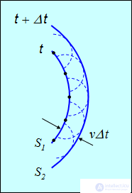
Fig. 3.1. Illustration of Huygens's principle: every point that the wave disturbance has reached
can be regarded as a source of secondary waves
Huygens's principle also applies to elastic waves. In fact, we have already once made use of this principle when we constructed the front of a shock wave — the Mach cone — for a source moving at supersonic speed. Exactly the same construction describes the emission of electromagnetic waves (light) by a charged particle moving at a speed exceeding the speed of light. In vacuum this would be impossible, since the speed of light in vacuum c is the limiting speed for any material object. But in a medium the speed of light is lower: it is equal to

where n > 1 is the refractive index of the medium). If the speed of the electron ve is greater than the speed of light in the medium, then the electron radiates energy at an angle  to the direction of motion

As with sound, a cone is formed with a half-angle 

— the Cherenkov cone. The formulas are analogous to those obtained for motion at supersonic speed, except that the speed of sound v is replaced by the speed of light c/n in the given medium. This phenomenon — the Cherenkov–Vavilov effect — brought the Nobel Prize to P.A. Cherenkov for its experimental discovery and to I.E. Tamm and I.M. Frank for its theoretical explanation. Nowadays this effect is used in practice in particle detectors.
The corpuscular theory very simply explained the phenomena of geometrical optics, described in terms of the propagation of light rays. From the point of view of the wave theory, rays are the normals to the wavefront. Huygens's principle also makes it possible to explain the laws of geometrical optics on the basis of wave concepts of the nature of light.
The law of reflection
When light waves reach the boundary between two media, the direction of their propagation changes. If they remain in the same medium, then reflection of light occurs.
|
Reflection of light — is a change in the direction of a light wave upon incidence on the boundary between two media, as a result of which the wave continues to propagate in the first medium. |
The law of reflection of light is well known:
|
The incident ray, the perpendicular to the boundary between two media at the point of incidence, and the reflected ray lie in the same plane, and the angle of incidence equals the angle of reflection. |
The directions of propagation of the incident and reflected waves are shown in Fig. 3.2.
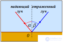
Fig. 3.2. Reflection of light from a plane surface
The law of reflection can be derived from Huygens's principle. Indeed, suppose that a plane wave, propagating in an isotropic medium, falls on the boundary between two media AC (Fig. 3.3).
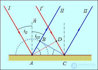
Fig. 3.3. Application of Huygens's principle to the derivation of the law of reflection
It is sufficient to consider two parallel rays I and  in the incident beam. The angle of incidence is the angle
  between the normal n to the interface and the incident ray I. The plane front AD of the incident wave will first reach the interface between the two media at point A, which becomes a source of secondary waves. According to Huygens's principle, a spherical wave will propagate from it, as from a center. After a time
 ,
,
that is, with a time delay of  , the ray
  from the incident beam will arrive at point C, which at that moment
  will likewise become a source of a secondary wave. But by this moment the secondary spherical wave propagating from point A will already have a radius
  (as it should:
  ). We now know the positions of two points of the front of the reflected wave — C and B. To avoid cluttering the figure, we do not show the secondary waves emitted by points between A and C, but the line CD will be tangent to (the envelope of) all of them. Hence CB is indeed the front of the reflected wave. Its direction of propagation (rays II and
  ) is orthogonal to the front CD. From the equality of triangles ABC and ADC it follows that the angles are equal

which, in turn, leads to the law of reflection

Figure 3.4 shows an interactive model of the reflection of light.
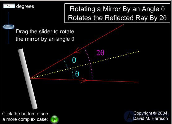
Fig. 3.4. Studying the law of reflection of light
The law of refraction
If light waves reach the boundary between two media and penetrate into the other medium, then the direction of their propagation also changes — refraction of light occurs.
|
Refraction of light — is a change in the direction of propagation of a light wave upon passing from one transparent medium into another. |
The directions of propagation of the incident and refracted waves are shown in Fig. 3.5.
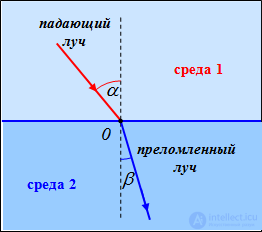
Fig. 3.5. Refraction of light at a plane boundary between two transparent media
The law of refraction states:
|
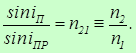
The incident ray, the perpendicular to the boundary between the media at the point of incidence, and the refracted ray lie in the same plane, and the ratio of the sine of the angle of incidence to the sine of the angle of refraction is constant for a given pair of media and equal to the refractive index of the second medium relative to the first
|
Here  is the refractive index of the medium in which the refracted wave propagates, and
  is the refractive index of the medium in which the incident wave propagates.
The law of reflection also follows from Huygens's principle. Consider (Fig. 3.6) a plane wave (front AB), propagating in a medium with refractive index  , along direction I at speed

This wave falls on the boundary with a medium in which the refractive index is equal to  , and the propagation speed

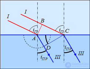
Fig. 3.6. Deriving the law of refraction of light using Huygens's principle
The time taken by the incident wave to traverse the path BC, is equal to

In this same time, the front of the secondary wave, excited at point A in the second medium, reaches points on a hemisphere of radius

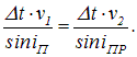
According to Huygens's principle, the position of the front of the refracted wave at this moment in time is given by the plane DC, and its direction of propagation — by the ray III, perpendicular to DC. From the triangles  and
and  it follows that
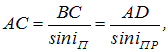
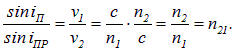
whence
|
|
|
(3.1) |
Thus, the law of refraction of light is written as:
|
|
|
(3.2) |
Figure 3.7 shows an interactive model of the refraction of light at the boundary between two media.
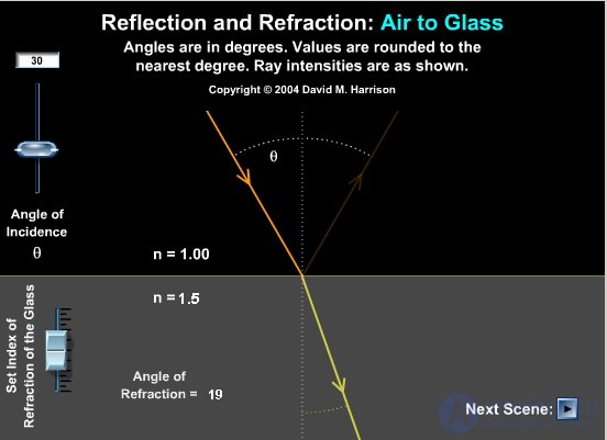
Fig. 3.7. Studying the law of refraction
For a further illustration of the application of Huygens's principle, let us consider an example.
Example. A ray of light falls normally on a plane boundary between two media. The refractive index of the medium increases continuously from its left edge to its right edge (Fig. 3.8). Let us determine how the ray of light will travel in this inhomogeneous medium.
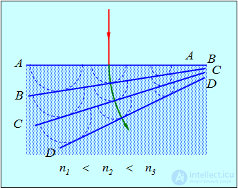
Fig. 3.8. Bending of a ray of light in an inhomogeneous medium
Suppose the wavefront AA has approached the boundary between the media. The points of the interface can be regarded as centers of secondary waves. After a time  the emitted secondary spherical waves reach points at a distance
  from the front AA. Since the refractive index of the medium increases from left to right, these distances decrease from left to right. The envelope of the secondary waves — the new front BB — will turn. If we now take the points of the front BB as sources of secondary waves, then after a time
  they will generate waves forming the front CC. It is turned even further. Its points generate the front DD and so on. Drawing the normal to the wavefronts at different moments in time, we obtain the path of the light ray in a medium with a variable refractive index (the green line). It can be seen that the ray bends toward increasing refractive index. An analogy: if you brake the left wheels of a car, it will turn left. For light, the degree of «braking» grows with increasing refractive index of the medium:
  .
.
This problem is related to a phenomenon observed at sea. When the wind blows from the shore, a so-called «zone of silence» sometimes arises: the sound of a ship's bell does not reach the shore. It is usually said that the sound is carried away by the wind. But even in a strong gale, the wind speed is about 10 times less than the speed of sound, so the wind cannot «carry away» the sound. The explanation is that, owing to friction, the speed of the headwind at the sea surface is lower than at altitude. Therefore the speed of sound near the surface is greater, and the line of sound propagation curves upward, not reaching the shore.
Fermat's principle.
Thus, wave optics is able to explain the phenomena of reflection and refraction of light just as successfully as geometrical optics. The latter, which treats phenomena on the basis of the laws of ray propagation, is founded on Fermat's principle:
|
Light propagates along the path that requires the minimum time to traverse. |
To traverse a segment of the path  light requires a time
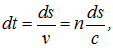
where v=c/n - is the speed of light in the medium. Thus, the time t, taken by light to travel from point 1 to point 2, is equal to
|
|
|
(3.3) |
Let us introduce a quantity with the dimension of length, called the optical path length:
|
|
|
(3.4) |
The proportionality between t and L allows us to formulate Fermat's principle as follows:
|
Light propagates along the path whose optical length is minimal. |
Consider the path of light from point S to point C after reflection from the plane AB (Fig. 3.9).
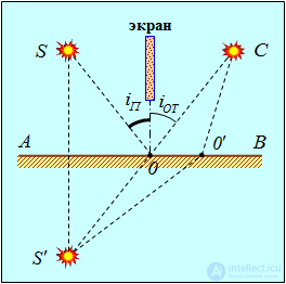
Fig. 3.9. Application of Fermat's principle to the reflection of light
Direct passage of light from S to C is impossible because of the screen. We need to find the point O, upon reflecting from which the ray will arrive at point C. The medium through which the ray passes is homogeneous. Therefore the minimality of the optical path length reduces to the minimality of its geometric length. Consider the mirror image S' of point S. The geometric lengths of the paths SOC and S'OC are equal. Therefore the minimality of the length SOC is equivalent to the minimality of the length S'OC. And the minimal geometric length of the path from S' to C will correspond to the straight line joining points S' and C. The intersection of this straight line with the interface between the media gives the position of point O. From this the equality of the angles follows:

that is, the law of reflection of light.
Let us now consider the phenomenon of refraction of light (Fig. 3.10).
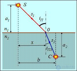
Fig. 3.10. Application of Fermat's principle to the refraction of light
Let us determine the position of the point O, at which the ray must be refracted, propagating from S to C, so that the optical path length L is minimal. The expression for L has the form
|
|
|
(3.5) |
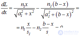
Let us find the value x, corresponding to the extremum of the optical path length:
|
|
|
(3.6) |
From this it follows that
|
|
|
(3.7) |
or

We have obtained the law of refraction of light.
Fermat's principle is a special case of the so-called principle of least action, which has applications in practically all areas of physics. Of all the possible motions of a system, the one that is actually realized is that for which a certain quantity (called the action) is minimal (more precisely, has an extremum). This reflects a certain «economy» of nature, which chooses the optimal paths for a system to pass from one state to another.





Comments