Electric circuit
In the previous topic we became acquainted with various sources of electric energy (current sources). Alongside them there are various consumers of electric energy: lamps, vacuum cleaners, computers and others. To deliver electric energy from sources to consumers, connecting conductors are needed, and to control the flow of energy, switching devices are needed: switches, circuit breakers, terminals, sockets, plugs and so on.
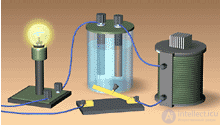
In physics and electrical engineering, a source of electric energy and its consumers, connected together by conductors, are called an electric circuit. On the left is shown a circuit for observing the thermal, chemical and magnetic effects of current simultaneously.
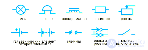
Later on we will have to use many electrical devices, connecting them into various circuits. To understand them better, we will use schematic drawings of circuits – electric circuit diagrams. Here are some conventional symbols that we will use:
Besides those shown in the figure, there are other symbols for electrical devices. We will become acquainted with them as needed.
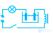
The figure above shows an electric circuit, and on the left – the diagram of this circuit. It contains: a lamp, a vessel with electrodes and liquid, an electromagnet, a switch and a pair of terminals to which the source of electric energy will be connected.
Questions
- Current sources are more correctly called ...
- Lighting fixtures, irons and other electrical appliances are ...
- Connecting wires serve the purpose of ...
- Switching devices are used for ...
- Examples of switching devices are ...
- An electric circuit in physics and engineering is ...
- The upper figure shows an electric circuit ...
- In physics and engineering, circuit diagrams are ...
- On circuit diagrams, all their elements have ...
- The upper and left-hand figures are about the same thing, since ...
Types of conductor connections in a circuit
Let us now study the types of conductor connections in a circuit.
All conductors used in electric circuits have conventional symbols for depiction on diagrams and can form series, parallel and mixed connections.
A connection can be series, parallel or mixed.
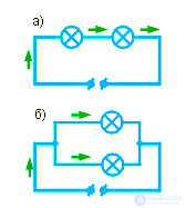
A series connection is called such a connection of conductors in which the loads are arranged one after another , having one common connection point .
A parallel connection is called a connection of conductors in which they are connected to each other, having two common points.
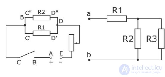
A mixed connection is called a connection containing sections of series and parallel connection
Look at the two diagrams a and b in the figure. If you were asked to assemble a circuit from a source of electric energy and two lamps, you would most likely proceed as shown in diagram a. Such a connection of two conductors is series. It is so named because, moving along the circuit from the «–» terminal to the «+» terminal, all electrons will pass through both lamps in sequence, that is, first through one lamp and then through the other.
But the lamps can also be connected as shown in diagram b. Such a connection of two conductors is parallel. This name emphasizes that, moving along the wires, all electrons will split into two groups, which will pass through the lamps in parallel, that is, independently of each other.
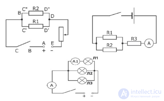
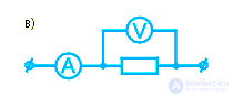
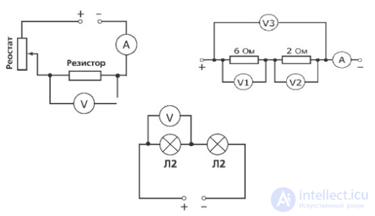
Mixed connection of electrical devices is also found in electric circuits. Diagram c shows a parallel connection of the devices «resistor» and «voltmeter». This pair of devices is connected in series with the device «ammeter» and the terminals for connecting the source of electric energy.
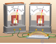
Let us assemble a circuit according to this diagram (see figure). On the left, as in the diagram, we place the ammeter, on the right – the voltmeter and the resistor. Two wires run off the edges of the figure; the terminals of the electric energy source are there.
What an ammeter, a voltmeter and a resistor are, we will learn a little later. For now it is important to remember: an ammeter is always connected in series, while a voltmeter is always connected in parallel with the section of the circuit where electrical measurements are being taken.
Examples of mixed-connection diagrams
Application and features of series connection
Features of a series connection of conductors
- Increasing the number of conductors increases their total resistance
- Each load receives only a part of the total voltage
- If one load fails, the operation of the entire circuit stops
The features of this connection allow it to be used for working with loads
rated for a voltage lower than the source voltage (Christmas tree lights and others)
Application and features of parallel connection
Features of a parallel connection
- Increasing the number of conductors decreases their total resistance
- Switching off one load does not interfere with the operation of the others
- All loads operate at the same voltage
The features of a parallel connection make it optimal in household and industrial electric circuits
A mixed connection is used in special electric circuits
Conclusions
- Series and parallel connection of conductors underlie any electric circuits.
- Knowledge of the laws of connections and their features makes it possible to navigate household electric circuits and calculate various characteristics of their loads.
Questions


Comments