
Lecture
|
Interference of waves — is the phenomenon of the amplification or attenuation of oscillations at different points in space (spatial redistribution of energy), observed when two or more waves are superimposed. |
Interference is possible for waves of any nature. Below, the manifestations of interference of electromagnetic (light) waves will be examined in the greatest detail. Interference of light is characterized by a regular alternation in space of regions of increased and decreased light intensity, which arise as a result of the superposition of so-called coherent light beams.
The superposition principle is valid for the electromagnetic field. Since light has an electromagnetic nature, applying the superposition principle means that the resulting electric (magnetic) field strength of two light waves passing through the same point is equal to the vector sum of the electric (magnetic) field strengths of each of the waves taken separately.
As is known, the intensity of an electromagnetic wave is proportional to the time-averaged value of the square of the amplitude of oscillations of the electromagnetic field strength vector:
|
|
|
(4.1) |
Therefore the intensity of a wave, being like any other field-nonlinear (in this case — field-quadratic) quantity, does not obey the superposition principle. There is no superposition principle for field-nonlinear quantities. If the field strength vectors add together, the intensities of the waves generally do not add together. Setting details aside, it can be stated that this is precisely the reason for the phenomenon known as interference of waves.
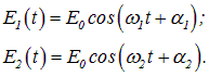
Let us consider two electromagnetic waves of the same frequency, which are superimposed on one another and excite two oscillations of the same direction:
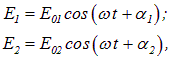
where  and
and  are the time-independent initial phases of the oscillations at the point under consideration
The amplitude of the resulting oscillation at a given point can be found using a vector diagram.
This amplitude E0 depends on the phase difference of the oscillations being added at the given point. In the case under consideration, where the wave frequencies are equal, the phase difference of the oscillations does not change over time and equals 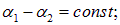 , and the resulting amplitude E0 likewise remains constant in time:
|
|
|
(4.2) |
|
Coherent waves — are waves that excite oscillations at points in space whose phase difference remains unchanged over time. |
Coherence — is the correlated course of several oscillatory or wave processes.
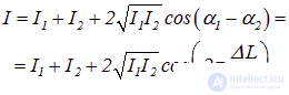
For coherent waves, the cosine of the phase difference has a value constant in time (though its own value at each point in space), so that the resulting intensity of light, as follows from (4.1) and (4.2), equals
|
|
|
(4.3) |
The last term in the expression obtained is called the interference term. Thus, when coherent light waves are superimposed, a redistribution of the light flux in space occurs, as a result of which maxima arise in some places and — minima of intensity in others. If the intensities of both interfering waves are equal ( ), then at the maxima
  , and at the minima
  .
.
If incoherent waves are superimposed, then at a given point in space the oscillations that add together have a phase difference that is not constant in time and, generally speaking, takes on random values. If, in this case, the randomly varying phase difference — over some time  — takes on all possible values within an interval of length
  , then the average (over the time
  ) value of the cosine in the interference term is zero, and the observed light intensity at all points in space is simply represented by the sum of the intensities of the two waves:
|
|
|
(4.4) |
When the intensities of the incoming waves are equal, we obtain  . When we switch on two identical light bulbs and the room is illuminated twice as brightly as by one of them, this means there is no interference and relation (4.4) holds. Thus,
|
a necessary condition for the observation of interference of waves is their coherence. |
A monochromatic plane electromagnetic wave is described by the following expression for the field strength at any point in space, defined by the position vector r:
|
|
|
(4.5) |
where E0,  ,
,  and
and  are constant quantities. However, every real light wave is formed by the superposition of oscillations of various frequencies, contained within a finite interval
  . According to the formula
  , the spread of frequencies
  corresponds to a spread of values of the wave number
  . It should be noted that the spread of the wave vector
  can also be associated with a spread in the directions of wave propagation, which is characterized by the vector quantity
  .
.
Let us first discuss temporal coherence, which is associated with the spread of frequencies  . Let us consider the case of the superposition, at some point in space, of two light oscillations with somewhat different frequencies
  :
:
|
|
|
(4.6) |
The interference term
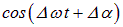
will, under the assumptions made, depend on time and on the frequency difference
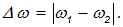
Every optical instrument by means of which the interference of light is observed (photographic film, the human eye, etc.) has a certain inertia, which is characterized by the time  needed by the instrument to register the interference pattern. In doing so, the optical instrument registers a pattern averaged over the time interval
  . If, during this time, the cosine in the interference term
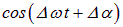
takes on, with equal probability, all values from –1 to +1, then the average value of the interference term will be zero. The interference pattern will not be visible, that is, the intensity registered by the instrument will turn out to be equal to the sum of the intensities produced at the given point by each wave separately. If, however, during the time  the value of the cosine remains practically unchanged, the instrument will register interference. Thus, to characterize the coherence properties of light waves, the coherence time
  is introduced, which is defined as the time during which the change in the phase difference of the waves being superimposed at the given point in space reaches the value
  :
:

When

the instrument will not detect interference, whereas when

the instrument will detect an interference pattern. During the coherence time  the wave propagates over a distance

called the coherence length.
To observe an interference pattern, beams of light from a single source are usually used, but ones that have traveled different distances to the point of observation. This means that the waves interfering were emitted by the source at different times. If the source frequency «fluctuates», then for a path difference of the waves to the point of observation  the difference in the emission times of the waves will be
  , which means that observing interference is impossible.
As an example, let us indicate typical values of the coherence length for a natural optical source with a narrow-band optical filter having a passband width  near the middle of the visible range (
 nm) and for a gas laser — a source of optical radiation with high temporal coherence, for which the passband width is two to three orders of magnitude smaller. In the first case, an estimate of the coherence length gives the value

while in the second case — for the laser —
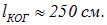
Thus, observation of an interference pattern from ordinary optical sources is possible only for small path differences, for example, in the interference in thin films, whereas the use of laser radiation substantially simplifies this task.
In the idealized case of the superposition of monochromatic waves with strictly fixed and equal frequencies ( ), the coherence time and coherence length become infinitely large, so that, naturally, under such conditions an interference pattern would be observed for any path difference.
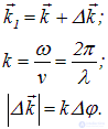
A change in the phase difference of oscillations can occur not only because of a spread of frequencies  , but also as a result of a spread of wave vectors
  . Therefore, alongside temporal coherence, defined by the coherence time, the concept of spatial coherence is introduced. The occurrence, at some point in space, of oscillations excited by waves with an entire set of vectors
  differing in direction, takes place if these waves are emitted by different portions of an extended light source.
Let us consider, for definiteness, a luminous disk AB, which is seen from point M at an angle  (Fig. 4.1)
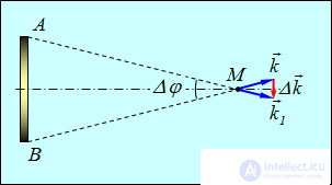
Fig. 4.1. Spatial coherence of light from an extended source:
the angle  characterizes the spread of wave vectors Ak
The angle  characterizes the spread of wave vectors
  . Thus, into the phase of the electromagnetic wave

one must substitute the expressions:
|
|
|
(4.7) |
Then

so that
|
|
|
(4.8) |
where  — is the projection of the position vector r onto the direction of the vector
  . In formulas (4.7) and below it is assumed that
  . The vector
  , as can be seen from the figure, can be regarded as parallel to the extended source and, accordingly, to the wave front.
Consequently, the phase of the oscillations changes on passing from one point of the wave surface to another. Let us introduce the distance  , upon displacement by which along the wave surface the phase change reaches the value
  :
:
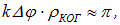
whence
|
|
|
(4.9) |
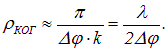
The distance  characterizes the spatial coherence of the wave and is called the coherence radius.
Let the length  characterize the spatial resolution of photographic film or of the human eye. The interference term is averaged over a portion of space with linear dimensions on the order of
  . When

the average value of the cosine is zero, which does not allow interference to be observed. In the opposite case, when

a distinct interference pattern is observed.
Let us give an example. The angular size of the Sun
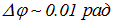 ,
,
approximately in the middle of the visible range the wavelength of visible light is

Consequently, the coherence radius of light waves arriving from the Sun is approximately equal to

With such a small coherence radius, it is impossible to directly observe interference of sunlight, since the resolving power of the human eye is only 0.1 mm. However, in 1807 T. Young carried out the first observation of interference precisely with sunlight. For this, he passed sunlight into a dark room through a small hole made with a thin needle. The hole reduced the angular size  of the light source by several orders of magnitude and, correspondingly, increased the coherence radius.
The mechanism of emission of electromagnetic waves consists in the fact that an atom in an excited state, upon transitioning to a lower energy level, emits an electromagnetic wave. The emission process lasts about  s. Thus, the atom emits a wave representing a portion of a sine wave (see Fig. 4.2), which is called a wave train.
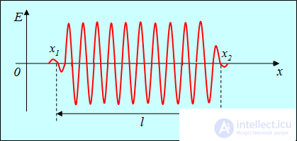
Fig. 4.2. A wave train
The length of the wave train in vacuum equals

Natural light is represented as a collection of mutually uncorrelated wave trains emitted by individual atoms. Therefore it is impossible to obtain interference from two different natural light sources. To obtain coherent light waves, the wave emitted by a single source is split, by one means or another, into two parts. After passing through different optical paths, these two parts of the one wave are superimposed on one another (Fig. 4.3).
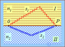
Fig. 4.3. Splitting of a wave from a natural source
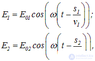
Suppose that the splitting into two coherent waves occurs at some point 0, lying on the boundary between two media I and II. Up to point P at which the interference pattern is observed, one wave travels a path s1 in a medium with refractive index n1, while the second wave travels a path s2 in a medium with refractive index n2. If the initial phases of both waves are zero, then at point P the waves will excite oscillations
|
|
|
(4.10) |
where
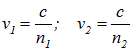
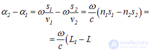
— are the phase velocities of the first and second waves, respectively. The phase difference of the oscillations at point P equals
|
|
|
(4.11) |
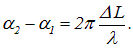
Expressing the angular frequency in terms of the wavelength l in vacuum

we find
|
|
|
(4.12) |
|
The optical path difference is the difference
between the optical path lengths traversed by the waves. |
Let us write the intensity of the resulting wave at point P in the form
|
|
|
(4.13) |
When the optical path difference equals a whole number of wavelengths in vacuum (or, equivalently, an even number of half-wavelengths), that is
|
|
|
(4.14) |
the oscillations at point P are in the same phase,  and an interference maximum is observed.
If the optical path difference equals an odd number of half-wavelengths, that is
|
|
|
(4.15) |
then the oscillations excited at point P by both waves are in antiphase,  and an interference minimum is observed.
Having established the general regularities, let us turn to a specific example of interference, in which the sources of light are two narrow parallel slits located sufficiently close to one another. Let these slits S1, and S2 be at a distance d from one another (Fig. 4.4).
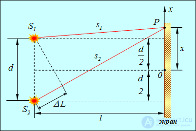
Fig. 4.4. Interference from two coherent light sources
Interference is observed at some point P on a screen located at a distance l from the light sources (l>>d,  ). The origin on the 0x axis is chosen at point 0, symmetric with respect to the slits.
The intensity at point P, located at a distance x from the origin, is determined by the optical path difference, which in this case (n = 1) equals the geometric path difference
|
|
|
(4.16) |
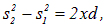
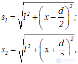
It can be seen that
|
|
|
(4.17) |
whence
or
|
|
|
(4.18) |
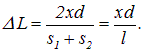
Taking into account that for l>>d

we obtain
|
|
|
(4.19) |
Using conditions (4.14) and (4.15) for the maxima and minima of interference, we arrive at the conclusion that at points with coordinates
|
|
|
(4.20) |
maxima will be observed, and at points
|
|
|
(4.21) |
— interference minima.
|
The width of an interference fringe — is the distance between neighboring minima of intensity. |
Taking (4.20) into account, the width of an interference fringe equals
|
|
|
(4.22) |
and  does not depend on the order of interference (the value of m) and is a constant quantity for given l, d,
To obtain an interference pattern, coherent light beams are required, and various artificial techniques are used to produce them. Before the advent of lasers, in all instruments for observing the interference of light, coherent beams were obtained, as noted above, by splitting and subsequently bringing together light rays originating from one and the same source. In practice this can be accomplished using screens with slits, mirrors, and refracting bodies (prisms). Let us discuss some of these methods.
Young's method
The light source is a brightly illuminated slit S, from which light falls on two equidistant slits s1, and s2, parallel to slit S (Fig. 4.5).
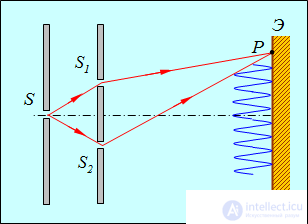
Fig. 4.5. Young's method of observing interference
Thus, slits S1 and S2 are sources of coherent light beams. Coherence, naturally, takes place provided that the distance between the slits  and
and  is smaller than the coherence radius of the light emerging from slit
  . The interference pattern can be observed on a screen E, located at some distance from the slits.
Fresnel's biplane mirror
A classic device that makes it possible to observe the interference of light is Fresnel's biplane mirror (Fig. 4.6).
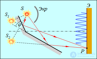
Fig. 4.6. Fresnel's biplane mirror
Light emitted by source S is reflected from two mirrors positioned at an angle close to 180° (the angle  is sufficiently small). As a result, two light beams are obtained, which propagate from two virtual sources S1 and S2, whose radiation, given a sufficiently small transverse size of the real source
  and a sufficiently small angle
  , will be coherent, since they are also images of one and the same real source S. In this case the rays going from S1 and S2 to the screen, having traveled different paths, produce an interference pattern. (The opaque screen Scr blocks the direct path of light from source S to the screen E.)
Fresnel's biprism
Fresnel's biprism consists of two identical prisms with a small refracting angle, joined base to base so that a common flat face is formed (Fig. 4.7).
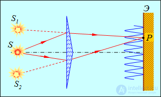
Fig. 4.7. Fresnel's biprism
Light from source S is refracted in both prisms, as a result of which coherent light beams propagate beyond the biprism, appearing to emanate from two virtual sources S1 and S2, just as in the case of Fresnel's biplane mirror. Thus, on the screen a superposition of coherent light beams occurs and an interference pattern is observed. Fulfillment of the coherence conditions, as in the preceding examples, is ensured by the small transverse dimensions of the real source  and by the smallness of the refracting angle of the biprism.
The iridescent coloring of soap bubbles or gasoline films on water arises as a result of the interference of sunlight reflected by the two surfaces of the film.
Let a plane monochromatic wave fall onto a plane-parallel transparent film with refractive index n and thickness d, at an angle  and with wavelength
  (Fig. 4.8).
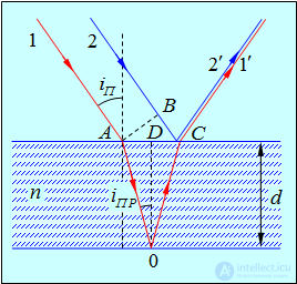
Fig. 4.8. Interference of light in a thin film
The interference pattern in the reflected light arises because of the superposition of two waves reflected from the upper and lower surfaces of the film. Let us consider the addition of waves emerging from point C. A plane wave can be represented as a bundle of parallel rays. One of the rays of the bundle (2) falls directly on point C and is reflected (2') from it upward at an angle equal to the angle of incidence  . The other ray (1) reaches point C by a more complicated path: it first refracts at point A and propagates within the film, then reflects from its lower surface at point 0 and, finally, emerges, after refracting, outward (1') at point C at an angle equal to the angle of incidence
  . Thus, at point C the film sends two parallel rays upward, of which one arose owing to reflection from the lower surface of the film, and the second — owing to reflection from the upper surface of the film. (Beams arising as a result of multiple reflections from the surfaces of the film are not considered, in view of their low intensity.)
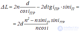
The optical path difference acquired by rays 1 and 2 before they converge at point C equals
|
|
|
(4.23) |
Setting the refractive index of air  and taking into account the relations
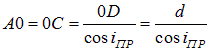
and

as well as
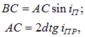
we find
|
|
|
(4.24) |
Let us use the law of refraction of light
|
|
|
(4.25) |
whence
|
|
|
(4.26) |
Thus,
|
|
|
(4.27) |
In addition to the optical path difference  , one must also take into account the change in phase of the wave upon reflection. At point C at the «air – film» boundary, reflection occurs from an optically denser medium, that is, from a medium with a larger refractive index. For not too large angles of incidence, the phase in this case undergoes a change of
  . (The same jump in phase occurs upon reflection of a wave traveling along a string, from its fixed end.) At point 0 at the «film – air» boundary, the light is reflected from an optically less dense medium, so that no phase jump occurs.
As a result, an additional phase difference arises between rays 1' and 2', , corresponding, as follows from formula (4.12), to an optical path difference  , which can be accounted for by decreasing or increasing the quantity by half a wavelength in vacuum.
Consequently, when the relation
|
|
|
(4.28) |
holds, a maximum of interference is obtained in the reflected light, whereas in the case
|
|
|
(4.29) |
a minimum is observed in the reflected light.
Thus, when light falls on a gasoline film on water, depending on the viewing angle and the film thickness, an iridescent coloring of the film is observed, indicating the amplification of light waves of certain wavelengths l. Interference in thin films can be observed not only in reflected light, but also in transmitted light.
As already noted, for an observable interference pattern to arise, the optical path difference of the interfering waves must not exceed the coherence length  , which places a restriction on the film thickness.
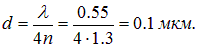
Example. A beam of white light falls normally on a soap film (n = 1.3) located in air. Let us determine the smallest thickness d of the film at which the reflected light of wavelength  μm will be maximally amplified as a result of interference.
From the interference maximum condition (4.28) we find the following expression for the film thickness

(angle of incidence  ). The minimum value of d is obtained at
  :
:
Let us consider the reflection of light from a thick plane-parallel glass plate and a plano-convex lens with a large radius of curvature that are in contact with one another (Fig. 4.9). The role of the thin film, from the surfaces of which coherent waves are reflected, is played by the air wedge (gap) between the plate and the lens. (Owing to the large thickness of the plate and the lens, the waves reflected from the other surfaces do not produce interference patterns.)
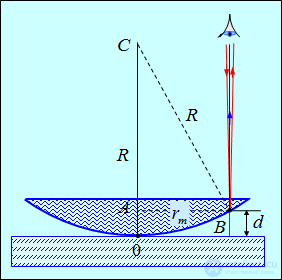
Fig. 4.9. Observation of Newton's rings
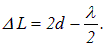
Under normal incidence of light, the interference pattern has the form of concentric circles (Newton's rings). Each of these interference fringes arises as a result of reflection from portions of the air wedge having the same thickness (owing to which they are called interference fringes of equal thickness). Let us determine the radii of Newton's rings obtained when light falls normally on the plate. In this case  and the optical path difference equals (in the air gap
  ):
):
|
|
|
(4.30) |
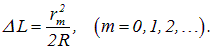
From the triangle  we have (R>>d):
|
|
|
(4.31) |
or
|
|
|
(4.32) |
Thus, for the bright rings (maxima) the path difference will be
|
|
|
(4.33) |
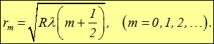
From this follows the expression for the radii of the bright rings:
|
|
|
(4.34) |
The radii of the dark Newton's rings are obtained equal to
|
|
|
(4.35) |
At the point of contact between the plate and the lens, that is, at  ,
,  , a minimum of intensity is observed, caused by a change in the phase of the oscillations by
  upon reflection of the light wave from the plate.
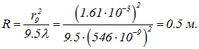
Example. In light reflected with wavelength  nm, the radii of two bright Newton's rings were measured and found to be 0.161 cm and 0.284 cm. It was calculated that 19 other bright rings lie between these rings. Let us determine the radius of curvature of the lens.
Let the smaller measured Newton's ring have order m, then the order of the larger one equals m + 20. Using (4.34):
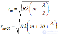
Squaring these equalities and dividing one by the other, we obtain
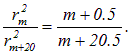
From this we find the order m of the smaller of the mentioned Newton's rings:
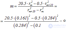
and the sought radius of curvature of the lens will equal
























Comments