
Lecture
Electric current is the flow caused by the ordered motion of electrically charged particles. The direction of motion of the charges is taken as the direction of the electric current. Electric current can be short-term or long-term.
During a lightning discharge, an electric current can arise, which is called short-term. But to sustain a current over a long period of time, an electric field and free carriers of electric charge must be present.
An electric field is created by bodies charged with opposite signs. Current strength is the ratio of the charge carried through the cross section of a conductor over an interval of time to that interval of time. It is measured in amperes.
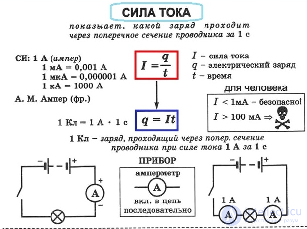
Fig. 1. Formula for current strength
Under normal conditions, gas molecules do not conduct electric current. They are insulators (dielectrics). However, if the ambient conditions are changed, gases can become conductors of electricity. As a result of ionization (through heating or under the action of radioactive radiation), an electric current arises in gases, which is often replaced by the term «electric discharge».
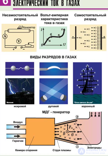
Discharges in a gas can be self-sustained or non-self-sustained. A current begins to exist when free charges appear. Non-self-sustained discharges exist only as long as an external force acts on them, that is, an external ionizer. That is, if the external ionizer stops acting, the current also stops.
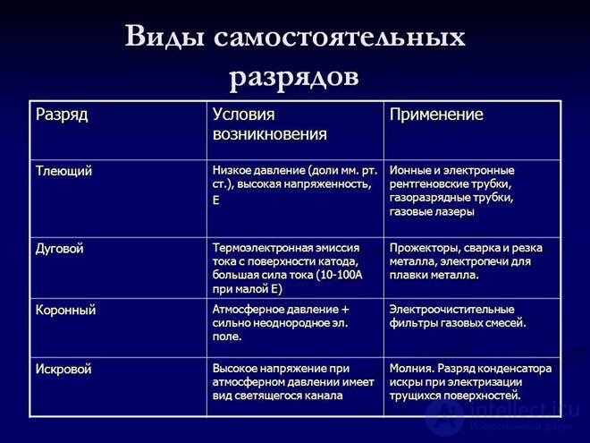
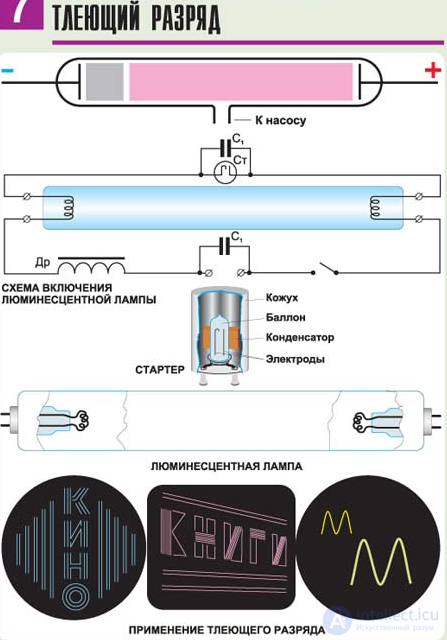
A self-sustained discharge of electric current in gases exists even after the action of the external ionizer has ceased. Self-sustained discharges in physics are divided into quiet, glow, arc, spark, and corona discharges.
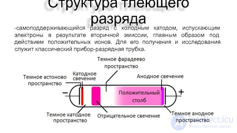
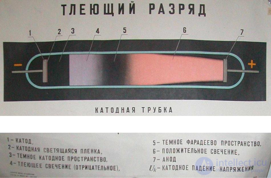
Fig. 2. Glow discharge
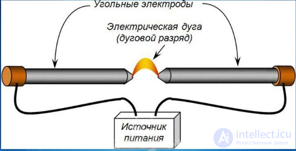
Fig. 3. Arc discharge
Atoms and molecules of gas are neutral in themselves. They become charged under external influence. Briefly speaking, electric current in gases represents the directed motion of particles (positive ions toward the cathode and negative ions toward the anode). It is also important that upon ionization of a gas, its conducting properties improve.
Plasma. At a sufficiently high temperature, any substance evaporates, turning into a gas. As the temperature increases further, thermal ionization intensifies. Neutral gas molecules break down into their constituent atoms, which subsequently turn into ions. In addition, ionization of a gas can be caused by its interaction with electromagnetic radiation (photoionization) or by bombardment of the gas with charged particles, for example, ionization by electron impact.
Plasma — a fully or partially ionized gas in which the concentrations of positive and negative charges practically coincide, that is, the average densities of positive ρ+ and negative ρ– charges are equal in magnitude: ρ+ = |ρ−|.
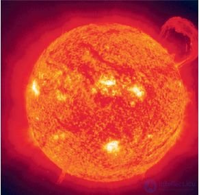
Fig. 214
Depending on the degree of ionization, a distinction is made between partially ionized and fully ionized plasma. Depending on the speed of thermal motion of the charged particles, a distinction is made between low-temperature (< 105 K) and high-temperature (> 106 K) plasma. An example of low-temperature plasma is the plasma formed by all types of electric discharge in gases. Stars are giant clumps of high-temperature plasma.
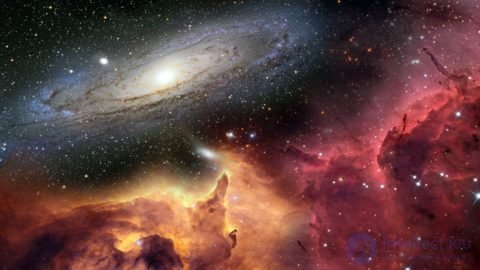
Plasma fills the cosmic space between stars and galaxies and is the most widespread state of matter in the Universe (Fig. 214). The concentration of plasma in intergalactic space is very low, on average one particle per cubic meter. The upper layer of the Earth's atmosphere is also a weakly ionized plasma. The cause of ionization is ultraviolet and X-ray radiation from the Sun and other stars, fast charged particles, and so on.
Regardless of the method of production, plasma as a whole is electrically neutral. The conductivity of plasma increases with an increasing ratio of the number of ionized atoms (molecules) to their total number. Fully ionized plasma approaches superconductors in its conductivity.
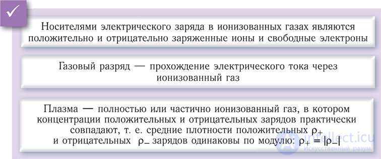
Plasma is an ionized gas formed from charged ions and electrons and from neutral atoms.
Interesting to know! Once no neutral particles remain in the gas, the plasma becomes fully ionized.
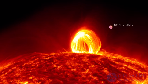
Interesting to know! Heating is not the only way to obtain plasma. The plasma state in gases can also be caused by: cosmic rays, ultraviolet and radioactive radiation, a passing beam of fast electrons, and so on.
It turns out that plasma is the fourth state of matter, most closely resembling a gas and behaving in much the same way under many conditions.
In a plasma television, `bubbles` of neon and xenon gases are placed in hundreds and hundreds of thousands of small cells, sandwiched between two glass panels. Long electrodes are also arranged between the panels on both sides of the cells. `Address` electrodes are located behind the cells, along the rear glass panel. Transparent electrodes are coated with a dielectric and a protective film of magnesium oxide (MgO). They are positioned above the cells, along the front glass panel.
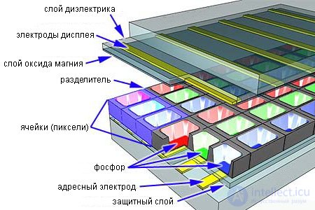
Both `grids` of electrodes cover the entire display. The display electrodes are arranged in horizontal rows along the screen, while the address electrodes are arranged in vertical columns. As can be seen in the figure below, the vertical and horizontal electrodes form the basic grid.
In order to ionize the gas in a particular cell, the plasma display's computer charges the electrodes that intersect at that cell. It does this thousands of times in a fraction of a second, charging each cell of the display in turn.
When the intersecting electrodes are charged, an electric discharge passes through the cell. The stream of charged particles causes the gas atoms to release photons of light in the ultraviolet range.
The photons interact with the phosphor coating on the inner wall of the cell. As is known, phosphor is a material that itself emits light under the action of light. When a photon of light interacts with a phosphor atom in the cell, one of the atom's electrons moves to a higher energy level. The electron then shifts back, releasing a photon of visible light in the process.
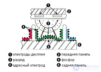 Pixels in a plasma panel consist of three sub-pixel cells, each with its own coating – of red, green, or blue phosphor. During operation of the panel, these colors are combined by the computer, creating new pixel colors. By changing the pulse rhythm of the current passing through the cells, the control system can increase or decrease the glow intensity of each sub-pixel, creating hundreds and hundreds of different combinations of red, green, and blue.
The main advantage of manufacturing plasma displays is the ability to create thin panels with wide screens. Since the glow of each pixel is determined individually, the image turns out to be remarkably bright, even when viewed from any angle. Normally, the saturation and contrast of the image are somewhat inferior to the best CRT television models, but they fully meet the expectations of most buyers. The main drawback of plasma panels is their price. It is impossible to buy a new plasma panel for less than a couple thousand dollars, and hi-end models will cost tens of thousands of dollars. However, over time the technology has improved significantly, and prices continue to fall. Plasma panels are now beginning to confidently push out CRT televisions, especially noticeably in wealthy, technologically developed countries. In the near future, `plasma` will make its way even into the homes of less affluent buyers.
Plasma panels are somewhat similar to CRT televisions – the display coating uses a phosphor-containing compound capable of glowing. At the same time, like LCDs, they use a grid of electrodes with a protective magnesium oxide coating to transmit the signal to each pixel cell. The cells are filled with inert, so-called `noble` gases – a mixture of neon, xenon, and argon.
The electric current passing through the gas makes it glow. In essence, a plasma panel is a matrix of tiny fluorescent lamps controlled by the panel's built-in computer. Each pixel cell is a kind of capacitor with electrodes. The electric discharge ionizes the gases, turning them into plasma – that is, an electrically neutral, highly ionized substance consisting of electrons, ions, and neutral particles. Being electrically neutral, plasma contains an equal number of electrons and ions and is a good conductor of current. After the discharge, the plasma emits ultraviolet radiation, which makes the phosphor coating of the pixel cells glow. The red, green, or blue component of the coating.
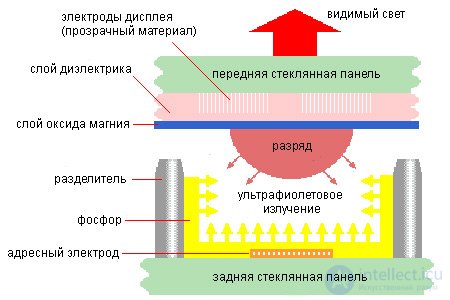
In fact, each pixel is divided into three sub-pixels, containing red, green, or blue phosphor. To create a variety of color shades, the glow intensity of each sub-pixel is controlled independently. In picture-tube televisions this is done by varying the intensity of the electron stream; in `plasma`, it is done using 8-bit pulse code modulation. The total number of color combinations in this case reaches 16,777,216 shades.
The fact that plasma panels are themselves a source of light provides excellent vertical and horizontal viewing angles and excellent color reproduction (unlike, for example, LCDs, whose screens usually require backlighting of the matrix). However, ordinary plasma displays normally suffer from low contrast. This is due to the need to continuously supply a low-voltage current to all the cells. Without this, the pixels would `turn on` and `turn off` like ordinary fluorescent lamps, that is, very slowly, unacceptably increasing response time. Thus, the pixels must remain switched off while at the same time emitting low-intensity light, which of course cannot help but affect the display's contrast. In the late 1990s, Fujitsu managed to somewhat ease the severity of the problem, improving the contrast of its panels from 70:1 to 400:1. By 2000, some manufacturers were claiming contrast ratios of up to 3000:1 in their panel specifications; now it is already 10000:1+.
The manufacturing process for plasma displays is somewhat simpler than that for LCDs. Compared with the production of TFT LCD displays, which requires the use of photolithography and high-temperature technologies in sterile clean rooms, `plasma` can be produced in dirtier workshops, at low temperatures, using direct printing. Nevertheless, the lifespan of plasma panels is short – quite recently the average panel lifetime was 25,000 hours; now it has almost doubled, but this does not remove the problem. Per hour of operation, a plasma display costs more than an LCD. For a large presentation screen the difference is not very significant, but if numerous office computers are equipped with plasma monitors, the advantage of LCD becomes obvious to the purchasing company.
Another important drawback of `plasma` is the large size of the pixels. Most manufacturers are unable to create cells smaller than 0.3 mm – which is larger than the grain of a standard computer monitor. It seems unlikely that the situation will improve for the better in the near future.
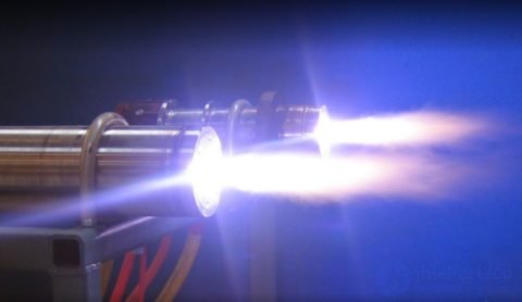
There are two types of plasma:
Both types are characterized by high electrical conductivity and strong interaction with surrounding electromagnetic and electric fields.
Interesting to know! In the universe, 99% of matter is plasma.
If two electrodes are placed in a vessel filled with plasma, then if there is an electric field between them, current will flow through the plasma – negative ions move toward the positively charged electrode, and vice versa. This process is accompanied by various optical and thermal phenomena. This phenomenon is called a gas discharge.
Low-temperature gas-discharge plasma, formed during glow, spark, and arc discharges in gases, is widely used in various light sources, in gas lasers, for welding, cutting, melting, and other types of metal processing.
The main practical interest in plasma physics is connected with solving the problem of controlled thermonuclear fusion – the process of fusion of light atomic nuclei at high temperatures under controlled conditions. The energy output of the reactor is 105 kW/m3 in the reaction
 )
)
at a plasma density of 105 cm-3 and a temperature of 108 K.
Confining high-temperature plasma is proposed (1950, USSR, I. E. Tamm, A. D. Sakharov) by means of a strong magnetic field in a toroidal chamber with magnetic coils, abbreviated as tokamak.
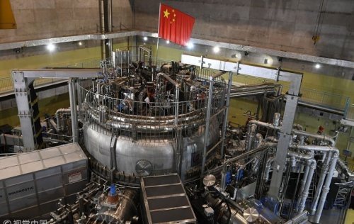
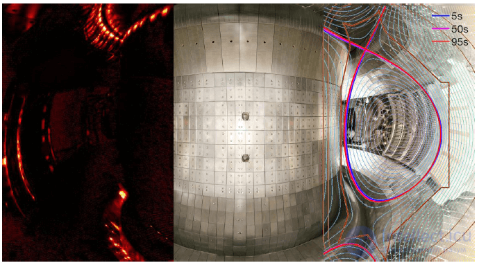
Interior view of a tokamak
Figure 8.11 shows a diagram of a tokamak: 1 – primary winding of the transformer; 2 – toroidal magnetic field coils; 3 – liner, a thin-walled inner chamber for equalizing the toroidal electric field; 4 – toroidal magnetic field coils; 5 – vacuum chamber; 6 – iron core (magnetic circuit).
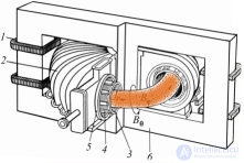
Fig. 8.11
At present, within the framework of the world thermonuclear program, the newest systems of the tokamak type are being intensively developed. For example, the first Russian spherical tokamak «Globus-M» has been built in St. Petersburg. Construction of a large TM-15 tokamak is planned, for research into controlling the plasma configuration. Construction has begun on the Kazakhstani KTM tokamak for developing thermonuclear power technologies. Figure 8.12 shows a cross-sectional diagram of the KTM tokamak and its view with the vacuum chamber.
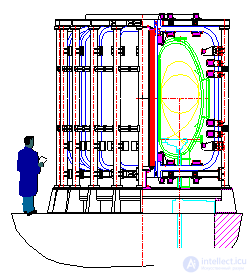
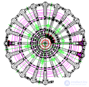
Fig. 8.12
Achieving a controlled thermonuclear reaction in high-temperature plasma will in the future allow humanity to obtain a practically inexhaustible source of energy.
Low-temperature plasma (T ~ 103 K) is used in gas-discharge light sources, gas lasers, and thermionic converters of thermal energy into electrical energy. It is possible to create a plasma engine, effective for maneuvering in outer space and for long-duration space flights.
Plasma serves as the working fluid in plasma rocket engines and MHD generators.
The motion of plasma in a magnetic field is used in the method of direct conversion of the internal energy of an ionized gas into electrical energy. This method is implemented in a magnetohydrodynamic generator (MHD generator), the basic diagram of which is shown in Figure 8.13.
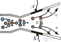
Fig. 8.13
A strongly heated ionized gas, formed as a result of fuel combustion and the enrichment of the combustion products with vapors of alkali metals, which promote an increase in the degree of ionization of the gas, passes through a nozzle and expands in it. In this process, part of the internal energy of the gas is converted into its kinetic energy. In a transverse magnetic field (in Figure 8.9 the vector  of the field's magnetic flux density is directed behind the plane of the drawing), positive ions are deflected under the action of the Lorentz force toward the upper electrode A, while free electrons are deflected toward the lower electrode K. When the electrodes are connected to an external load, an electric current flows in it, directed from the anode A, of the MHD generator, to its cathode K.
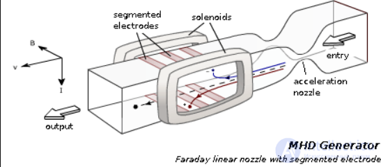
Faraday MHD generator with a linear nozzle and segmented electrodes:
entry — inlet opening for supplying the working fluid (ionized gas);
acceleration nozzle — nozzle for increasing the speed of the working fluid;
solenoids — solenoids for creating a magnetic field;
segmented electrodes — electrodes divided into segments to reduce the Hall effect;
output — outlet opening for discharging the working fluid;
red line — direction of motion of positively charged particles;
blue line — direction of motion of negatively charged particles;
B — magnetic flux density;
I — electric current;
v — speed of the working fluid
Theoretically, there are five directions for the industrial application of MHD generators:

Comments