
Lecture
As already noted earlier, under ordinary conditions dielectrics practically have no free charges, and therefore they are poor conductors of electric current (insulators) (Fig. 3.1). One might think that when a dielectric is placed in an electric field, nothing happens at all. However, this is not so: experiments have shown that the absence of free charges in dielectrics does not at all prevent them from reacting to an external field.
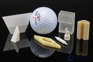
Fig. 3.1. Samples of dielectrics
Even M. Faraday discovered that if a dielectric plate is placed between the plates of a capacitor, the capacitance of the capacitor increases.
Fig. 3.2 shows an experiment demonstrating the dependence of the capacitance of a capacitor on the properties of the medium between its plates. A dielectric — a plate made of acrylic glass — is placed between the plates of a charged parallel-plate capacitor connected to an electrometer. In doing so, the electrometer reading decreases, which indicates an increase in the capacitance of the capacitor. After the dielectric is removed, the potential difference increases, returning to its previous value.
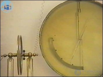
Fig. 3.2. Investigation of the dependence of the capacitance of a parallel-plate capacitor on the dielectric properties of the medium
When an insulator fills the entire space between the plates, the capacitance of the capacitor increases by a factor of  , where the dimensionless quantity
  takes different values for different materials. This quantity is called the permittivity of the given substance.
Let us again consider a parallel-plate capacitor. Let us charge it and insert a dielectric plate inside (Fig. 3.3).
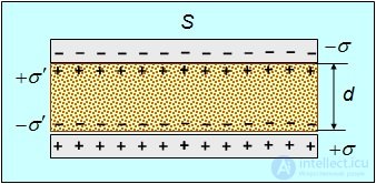
Fig. 3.3. A parallel-plate capacitor with a dielectric plate between the plates
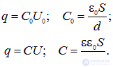
Quantities pertaining to the capacitor without a dielectric will be given the subscript 0. Since the charge of the capacitor does not change when a dielectric is placed inside it, we write the relations
|
|
(3.1) |
Here we used the experimental fact that the capacitance of a capacitor with a dielectric increases by a factor of . From relations (3.1) it follows that at the same charge on the plates, the potential difference U between them decreases by a factor of compared to the "empty" capacitor

Since the field in a parallel-plate capacitor is uniform, we obtain the following relation between the field strength E0 in vacuum and the field strength E in the dielectric
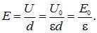
In other words, the presence of a dielectric between the plates can lead to a decrease in the electric field strength in the capacitor.
It should be noted that a simple decrease of the field by a factor of inside the dielectric occurs if and only if the surface of the dielectric is an equipotential surface of the field that would exist in the absence of the dielectric. This is precisely the case when a plane-parallel dielectric plate is placed in a parallel-plate capacitor, whose outer flat surfaces are parallel to the flat plates of the capacitor and, accordingly, coincide with two equipotential surfaces of the field of the capacitor without the dielectric. The same holds, for example, in the case of placing a spherical layer of dielectric with surfaces concentric with the plates of a spherical capacitor into that capacitor.
If, for example, a plane-parallel dielectric plate is placed in a uniform electric field (as in an ideal parallel-plate capacitor) so that its surfaces form some angle  with the direction of the field, and thus do not coincide with its equipotential surfaces, then the value of the field inside this plate will depend on the angle
  in a rather complicated way, and will be equal to
  only when
  . Nor should one think that introducing a dielectric into a field always leads to a decrease in the field strength — it may also increase: it all depends on the "geometry" of the problem. Figure 3.4 below shows that when a thin, long dielectric rod is placed in an electric field parallel to the field lines of the external field, the field strength outside the rod near its ends increases as a result of the appearance of "polarization" charges at the ends of the rod.
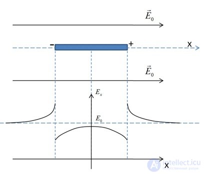
Fig. 3.4. Field strength on the axis of a thin dielectric rod
We observed a decrease in the potential difference between the plates and an increase in the capacitance of the capacitor in the problem solved above concerning a spherical capacitor with a metallic shell between the plates. There the reason for the decrease in the potential difference was clear: induced charges appeared on the shell, which compensated the external field from the plates. Accordingly, the electric field existed only in the space not occupied by the shell. If the shell occupied the entire volume of the capacitor, the potential difference between the plates and the field inside it would become zero.
There are no charges in a dielectric that are able to move throughout its entire volume, but the idea that additional charges of some kind arise on its surface (in this case they are called polarization or bound charges) seems attractive because of the possibility of explaining the experimental facts. We therefore adopt a macroscopic model, which of course must subsequently be justified at the microscopic level and verified in practice together with all its consequences. We shall assume that when a dielectric is placed in an electric field, polarization charges with density  arise on its surface (Fig. 3.5).
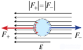
Fig. 3.5. A spherical particle in a uniform electric field of strength E.
The signs "+" and "–" show the bound charges that arise on the surface of the particle upon its polarization.
The electric forces acting on the positive (F+) and negative (F–) bound charges are equal
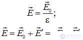
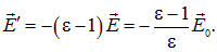
The polarization charges create an additional electric field  , directed opposite to the field from the charges on the plates (see Fig. 3.3). This explains the smaller magnitude of the resulting field E compared to the field E0. Indeed, for the simplest geometry of a parallel-plate capacitor (see the remark above about the shape of the dielectric surface), the change of the field in the dielectric reduces simply to a change in the magnitude of its strength by a factor of
|
|
(3.2) |
From this we find what part of the resulting field is created by the polarization charges, and what part by the charges on the plates
|
|
(3.3) |
The negative sign indicates the opposite direction of the field of the polarization charges. Knowing the relation between the surface charge density and the field strength it creates
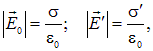
We find the density of the polarization charges
|
|
(3.4) |
Note that the case of a conductor corresponds to the limit

Indeed, in that case  , and the field inside the material is completely compensated, so we obtain
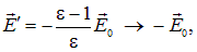
whence

Values of e for some dielectrics are given in the table (for gases — at standard conditions).
Table
Values of permittivity for some substances
|
Dielectric |
|
Dielectric |
|
|
Helium |
1.00007 |
Liquid helium |
1.047 |
|
Hydrogen |
1.00027 |
Liquid hydrogen |
1.23 |
|
Nitrogen |
1.00058 |
Liquid nitrogen |
1.43 |
|
Paper |
3.5 |
Transformer oil |
4.5 |
|
Porcelain |
6.5 |
Ice |
16 |
|
Ethyl alcohol |
25.1 |
Glycerin |
56.2 |
|
Water |
81.1 |
Strontium titanate |
310 |
|
|
|
|
|
Note that the same substances have different dielectric properties under different conditions. This means that to explain them, a theory must be constructed at the microscopic level, based on the properties of atoms and molecules and taking into account the state of the substance.
To understand the mechanism of the behavior of dielectrics in a field at the microscopic level, we must first explain how an electrically neutral system can react to an external electric field. The simplest case — the complete absence of charges — is of no interest to us. We know for certain that a dielectric contains electric charges — as part of atoms, molecules, ions of the crystal lattice, and so on. We shall therefore consider the next simplest construction, an electrically neutral system — two point charges +q and –q, equal in magnitude and opposite in sign, located at a distance l from each other. Such a system is called an electric dipole.
|
An electric dipole — is a system consisting of two point charges, equal in magnitude and opposite in sign, located at a distance l from each other (Fig. 3.6). |
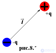
Fig. 3.6. Electric dipole
The electric field lines and equipotential surfaces of an electric dipole look as follows (Fig. 3.7, 3.8, 3.9)
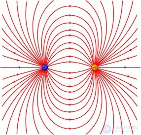
Fig. 3.7. Electric field lines of an electric dipole
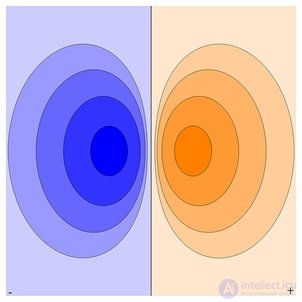
Fig. 3.8. Equipotential surfaces of an electric dipole
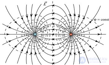
Fig. 3.9. Electric field lines and equipotential surfaces
The main characteristic of a dipole is its electric dipole moment. Let us introduce the vector l, directed from the negative charge (–q) to the positive charge (+q); then the vector p, called the electric moment of the dipole or simply the dipole moment, is defined as
|
|
(3.5) |
Let us consider the behavior of a «rigid» dipole — that is, one whose distance  does not change — in an external field E (Fig. 3.10).
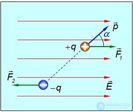
Fig. 3.10. Forces acting on an electric dipole placed in an external field
Let the direction of the dipole moment make, with the vector E, an angle . A force acts on the positive charge of the dipole, coinciding in direction with E and equal to F1 = +qE, while on the negative charge acts a force of opposite direction and equal to F2 = –qE. The torque of this pair of forces is equal to
|
|
(3.6) |
Since ql = p, then M = pE sin or in vector notation

(Recall that the symbol

means the vector (cross) product of vectors a and b.) Thus, for a constant dipole moment of the molecule ( ), the mechanical torque acting on it is proportional to the strength E of the external electric field and depends on the angle between the vectors p and E.
Under the action of the torque M, the dipole rotates, and in doing so work is done
|
|
(3.7) |
which goes toward increasing its potential energy. From this we obtain the potential energy of a dipole in an electric field

whence

or
|
|
(3.8) |
if we set const = 0.
From the figure it is evident that the external electric field tends to rotate the dipole so that the vector of its electric moment p coincides in direction with the vector E. In this case  , and, consequently, M = 0 as well. On the other hand, at the potential energy of the dipole in the external field takes its minimum value
  , which corresponds to a position of stable equilibrium. If the dipole is displaced from this position, a mechanical torque again arises that returns the dipole to its original position. Another equilibrium position, in which the dipole moment is directed against the field
 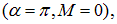 is unstable. In this case the potential energy takes its maximum value
  , and for small deviations from this position the resulting forces do not return the dipole but deflect it even further.
Fig. 3.11 shows an experiment illustrating the appearance of a torque of electric forces acting on a dielectric in an electric field. A torque acts on an elongated dielectric sample positioned at some angle to the field lines of the electrostatic field, tending to turn this sample so as to align it with the field. A dielectric rod, suspended at its midpoint inside a parallel-plate capacitor, turns perpendicular to its plates after a high voltage from an electrostatic machine is applied to them. The appearance of the torque is due to the interaction of the polarized rod with the electric field of the capacitor.
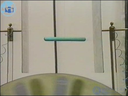
Fig. 3.11. Torque of electric forces acting on a dielectric in an electric field
In the case of a nonuniform field, the dipole under consideration will also be acted on by a resultant force Fres, tending to displace it. We shall consider here a particular case. Let us direct the x-axis along the field E. Suppose that under the action of the field the dipole has already turned to align with the field line, so that the negative charge is located at the point with coordinate x, and the positive charge is located at the point with coordinate x + l. Let us imagine that the magnitude of the field strength depends on the coordinate x. Then the resultant force Fres is equal to
|
|
(3.9) |
The same result can be obtained from the general relation

where the energy Π is defined in (3.8). If E increases with increasing x, then

and the projection  of the resultant force is positive. This means that it tends to draw the dipole into the region where the field strength is greater. This explains the well-known effect whereby neutral pieces of paper are attracted to an electrified comb. In a parallel-plate capacitor with a uniform field they would remain motionless.
Let us consider several experiments illustrating the appearance of a force acting on a dielectric placed in a nonuniform electric field.
Fig. 3.12 shows the dielectric being drawn into the space between the plates of a parallel-plate capacitor. In a nonuniform electrostatic field, forces act on the dielectric that draw it into the region of the stronger field.
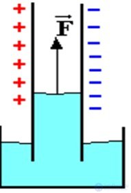
Fig. 3.12. Pulling a liquid dielectric into a parallel-plate capacitor
This is demonstrated using a transparent vessel containing a parallel-plate capacitor with a certain amount of liquid dielectric — kerosene — poured into it (Fig. 3.13). The capacitor is connected to a high-voltage power source — an electrostatic machine. When it operates, at the lower edge of the capacitor, in the region of the nonuniform field, a force acts on the kerosene, pulling it into the space between the plates. Therefore, the level of kerosene inside the capacitor settles higher than outside. After the field is switched off, the level of kerosene between the plates drops back to its level in the vessel.
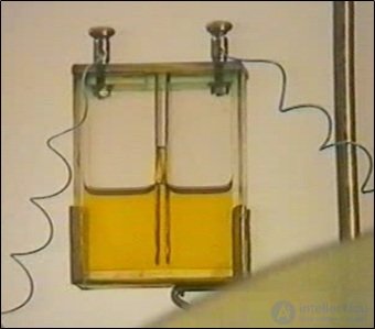
Fig. 3.13. Pulling kerosene into the space between the plates of a parallel-plate capacitor
Video 3.1. Experiment on pulling a liquid dielectric into a capacitor.
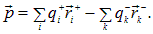
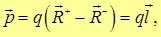
In real substances, dipoles formed by only two charges are rarely encountered. Usually we are dealing with more complex systems. But the concept of the electric dipole moment applies to systems with many charges as well. In this case the dipole moment is defined as
|
|
(3.10) |
where  ,
,  — the magnitude of the charge numbered i and the radius vector determining its location, respectively. In the case of two charges
 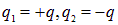 we arrive at the earlier expression
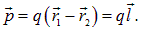
Let our system of charges be electrically neutral. It contains positive charges, whose magnitudes and locations we denote with the index «+». With the index «–» we denote the absolute magnitudes of the negative charges and their radius vectors. Then expression (3.10) can be written as
|
|
(3.11) |
In (3.11) the first term is summed over all positive charges, and the second — over all negative charges of the system.
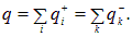
The electrical neutrality of the system means that the total positive charge equals the sum of the absolute magnitudes of all negative charges
|
|
(3.12) |
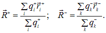
Let us now introduce the concept of the «center of charges» — positive R+ and negative R–
|
|
(3.13) |
Expressions (3.13) are analogous to the formulas for the center of mass in mechanics, and hence we call them the centers of positive and negative charges, respectively. With these notations and taking into account relation (3.12), we write the electric dipole moment (3.11) of the system of charges as
|
|
(3.14) |
where l is the vector drawn from the center of negative charges to the center of positive charges. The point of our exercise is to demonstrate that any electrically neutral system of charges can be represented as some equivalent dipole.
Any substance, regardless of its state of aggregation and the details of its atomic-molecular structure — for example, an atomic, molecular, or ionic crystal, etc. — ultimately consists of positively charged nuclei and negatively charged electrons.
Therefore the mechanism of polarization is a single one — it is the displacement of positive charges along the polarizing field and of negative charges against the polarizing field (Fig. 3.14). It is appropriate here to emphasize that the substance is polarized not by the external field  (see, for example, (3.2) above), but by the total field
  , created both by extraneous charges (not belonging to the dielectric) and by the polarized substance itself. We will not specifically emphasize this further.
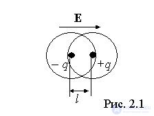
Fig. 3.14. Displacement of positive charges along the polarizing field
and of negative charges against the polarizing field
When studying the polarization properties of specific substances, it is reasonable and useful to single out the main features of the unified mechanism of charge displacement under the action of the polarizing field, which determine the result: the degree and character of the substance's polarization. This leads to the consideration of a whole series of «partial» polarization mechanisms, such as:
 s). There is no energy loss.
 s, without losses.
and many others.
A few words about the ionic polarization mentioned above, which takes place in crystals of the common-salt type NaCl. Under the action of the field the positively charged sodium ions Na+ and the negatively charged chlorine ions Cl– shift in opposite directions from their equilibrium positions, as a result of which each elementary cell of the crystal acquires an electric dipole moment. This example is useful in the following sense: no matter how complex the dielectric — in this case an ionic crystal — its polarization is caused by the displacement of positive and negative charges in opposite directions. The question is which specific charge carriers are capable of such displacement: free electrons in a metal, electrons strongly bound to the nuclei in the electron shell of neutral atoms or molecules in a gas or liquid, ions at the nodes of the crystal lattice, and so on. This is determined by how the dielectric is structured.
The processes occurring in a dielectric during its polarization can be understood based on the picture of the dielectric as a medium consisting of pairwise bound charges of opposite sign. Unlike conductors, dielectrics have no free charges that can move throughout the entire volume of the sample under the action of an external field. The charges making up the molecules of the dielectric are firmly bound to one another and are able to move only within their own molecule (or atom), that is, over a distance of order  cm.
cm.
In practically all cases where the dielectric consists of electrically neutral particles (atoms and molecules), regardless of its state of aggregation, it is possible to reduce all the «sub-mechanisms» of polarization to two types. For this, all atoms and molecules, and the dielectrics made of them, are conventionally divided into two classes:
 . These are noble-gas atoms
 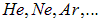 and symmetric molecules with a covalent bond of the type
  . Polyatomic nonpolar molecules also exist. Dielectrics consisting of such particles are called nonpolar dielectrics (Fig. 3.15);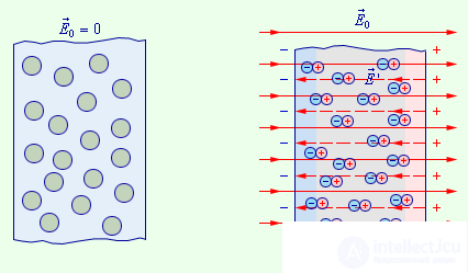
Fig. 3.15. Polarization of a nonpolar dielectric
 . These are asymmetric molecules with a covalent bond of the type
  , as well as molecules with an ionic bond of the type
 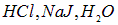 . Note that for molecules with an ionic bond
  is many times larger than for molecules with a covalent bond. Dielectrics consisting of such particles are called polar dielectrics (Fig. 3.16);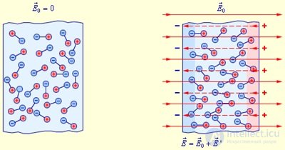
Fig. 3.16. Orientational mechanism of polarization of a polar dielectric
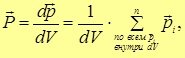
|
|
(3.15) |
Here  — the dipole moment vector of a single molecule, and the summation is carried out over all molecules located inside a physically infinitesimal volume
  . For example, let us consider a uniformly polarized sphere (Fig. 3.17).
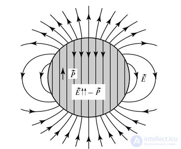
Fig. 3.17. Polarization and electric field of a uniformly polarized sphere
During the polarization of a nonpolar dielectric, the electron shell of the atom or molecule is deformed — the electrons are displaced against the polarizing field, and the nuclei are displaced along the field. A certain distance arises between the centers of positive and negative charges, which previously (in the absence of a polarizing field) coincided. As a result, the atom or molecule acquires a certain induced dipole moment.
It is more or less obvious that the induced dipole moment will be proportional to the magnitude of the external electric field. This can be understood by considering the behavior of the potential energy P(x) of the interaction of two particles, where x — is the distance between them. Let the equilibrium state correspond to a distance  (the particles are at the same point and the dipole moment is absent). For small deviations from the equilibrium position, in the Taylor expansion of the potential energy we can restrict ourselves to the first few terms

Taking into account that the first derivative at the equilibrium point  is equal to zero and that the second derivative at this point is positive
 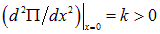 , we obtain that near the point of stable equilibrium the potential energy behaves as
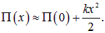
Accordingly, when deviating from this position a force arises
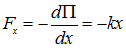 ,
,
similar to the elastic force when stretching a spring. If the charges in the molecule are «connected» by such a «spring», then when a field E is applied, the new equilibrium distance between the particles will be determined by the relation

As a result we find the magnitude of the dipole moment that arises under the action of the field
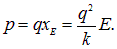
Multiplying the induced dipole moment by the concentration of polarized molecules N/V (N — their total number in volume V), we obtain the polarization of the dielectric
|
|
(3.16) |
If we write the polarization (3.16) in the form

where the constant (for a given substance)  is by definition the dielectric susceptibility of the substance, then for
  , within the framework of this model, the dielectric susceptibility can be calculated using the formula below

For molecules called polar molecules, the centers of positive and negative charges are shifted relative to one another, so such a molecule has an intrinsic dipole moment. When such a molecule is placed in an electric field, its electron shell is deformed, the distance between the centers of charges increases, and a certain induced dipole moment is added to the original intrinsic dipole moment. However, it can be shown that this additional induced dipole moment is much smaller than the intrinsic one. Of course, this holds if the polarizing field is much smaller than the field existing inside the molecule. In order of magnitude, the intramolecular field equals the atomic unit of electric field strength:  V/m. In the expression written above for the atomic unit of electric field strength,
  is the electron mass,
  its charge, and
  the Planck constant. Taking into account that, for example, the «breakdown» field strength — leading to a spark discharge — for dry air is only
  V/m, that is, five orders of magnitude smaller, we can state that in the overwhelming majority of experiments the induced dipole moment, when an intrinsic one is present, can be neglected. Further on, when considering the polarization of dipolar dielectrics, this effect (the induction of an additional moment) will not be taken into account.
The vectors of the intrinsic dipole moments of individual molecules are, in the ordinary state, randomly oriented due to thermal motion. Therefore, in the absence of an external electric field, the average total dipole moment of any physically infinitesimal volume of the dielectric is equal to zero. In other words, the dielectric is not polarized: its polarization  is equal to zero.
An external electric field tends to orient the dipole moments of the molecules parallel to the vector  , while thermal motion opposes this; the dielectric becomes polarized, and its polarization must depend on temperature, namely: it must decrease as the temperature rises. This dependence is calculated below, and it will also be shown that in the case of polar dielectrics too, their polarization is proportional to the strength of the polarizing field. Such polarization is called orientational (Fig. 3.18).
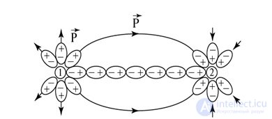
Fig. 3.18. Orientational polarization of a dielectric
In accordance with formula (3.8), the potential energy of a dipole in an external field E depends on the orientation of the dipole

According to the statistical Boltzmann law (Fig. 3.19), which describes the distribution of particles over energies in an external field under conditions of thermodynamic equilibrium, the number  of molecules whose dipole moment is oriented at an angle
  , to the external field, is determined as
|
|
(3.17) |
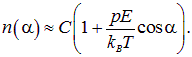
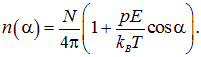
Here C — is a normalization constant, whose value we will find later, T — is the absolute temperature, and the Boltzmann constant — kB = 1.38·10–23 J/K. Owing to the smallness of the dipole moment of the molecules, for ordinary (not too low) temperatures the exponent is small, and we can expand the exponential in a Taylor series, keeping the first two terms
|
|
(3.18) |
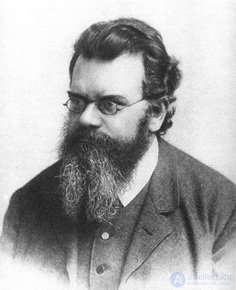
Fig. 3.19. L. Boltzmann (1844–1906) — Austrian physicist
We emphasize that the use of the approximate expression (3.18) and of all the conclusions following from it is justified at not too low temperatures, when  . An exact calculation using (3.17) instead of the approximate (3.18) presents no difficulty, and the reader may carry it out independently.
The integral  over the full solid angle must give the total number N of molecules in the system. Since the average value of the cosine is zero, only the first term in (3.18) is integrated. Since the value of the full solid angle is
  , we obtain

Now we know the constant C and can write expression (3.18) as
|
|
(3.19) |
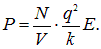
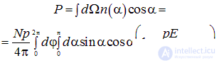
We need to determine the value of the projection of the total dipole moment onto the direction of the field (the other projections are obviously zero owing to the axial symmetry of the problem). The projection of the dipole moment of a single molecule equals pcosa, hence the total dipole moment P of all molecules in a unit volume equals
|
|
(3.20) |
The integral over  equals
  , and the integral over
  is evaluated using a change of variable
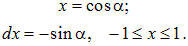
We then find
|
|
(3.21) |
From (3.21) it follows that in the case of dipolar orientational polarization of a substance as well, the polarization is proportional to the strength of the electric field. Moreover, we have found the dependence of the polarization on temperature. This is Curie's law, which is confirmed experimentally (Fig. 3.20).
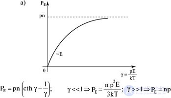
Fig. 3.20. Dependence of the polarization of a polar dielectric on temperature (exact solution)
Summarizing this section, we briefly repeat the main conclusions. An external electric field either creates dipole moments oriented along the field, or orients the dipole moments of individual molecules, and the dielectric acquires a certain macroscopic dipole moment. The vector  is called the polarization of the dielectric. It is proportional to the strength of the external electric field, and this relation can be represented as
|
|
(3.22) |
where  — is the proportionality coefficient (it is called the dielectric susceptibility). The coefficient is proportional to the concentration of particles in the dielectric and, in the case of a polar dielectric, depends on its temperature. Since the dimension of the dipole moment in SI is

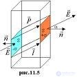
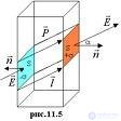
the polarization vector in SI is measured in C/m2. Its dimension coincides with the dimension of surface charge density. This suggests that the polarization vector is related to the density of polarization charges arising on the surface and in the volume of a dielectric placed in an external field (Fig. 3.21).
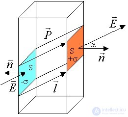
Fig. 3.21. Polarization vector and density of polarization charges
|
|
|
The proportionality between the polarization P and the strength E of the external electrostatic field is explained, in the case of electronic and ionic polarization, by the fact that as E increases, the dipole moments of individual atoms pi grow. In dipolar polarization, the degree of orientation of the vectors pi increases in proportion to the increase in the strength of the external electrostatic field. Above we found general formulas for the dielectric susceptibility for different types of polarization. It should be emphasized that they are valid for gases: we did not take into account the influence of molecules on one another, which is permissible for systems where the particles are not too densely packed. But the general conclusion remains valid for condensed media (liquids and solids) as well: under the action of an external electric field a unit volume of dielectric acquires a dipole moment P; in the simplest cases there is a linear dependence

All three mechanisms considered contribute to the total dielectric susceptibility of a dielectric:

It is usually rare for all the contributions to the dielectric susceptibility to be equally large. For example, in ionic crystals the dipolar part is absent altogether. Experimentally, the contribution of each part can be found by measuring the dielectric permittivities at different frequencies of the electromagnetic wave. At low frequencies (the static field, which we are now dealing with), all three contributions to the dielectric susceptibility make a contribution (Fig. 3.22).
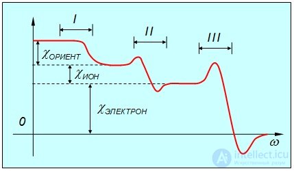
Fig. 3.22. Dependence of the total dielectric susceptibility of a dielectric 
on the frequency of the electromagnetic wave. The frequency ranges shown are:
I — the radio and microwave region, II — the infrared region, III — the ultraviolet region
As the frequency increases, the contribution of the dipolar part disappears first: the molecules will not manage to turn fast enough to follow the rapidly changing electric field of the wave. The transition to the new regime usually takes place at radio-range frequencies. With a further increase in frequency, the contribution of the ionic part disappears: ions are more inertial than electrons. In the optical frequency range the electronic part of the polarization dominates. On going to still higher frequencies — beyond the ultraviolet region — even the electron clouds will not manage to follow the changes of the electric field, and the polarizability of the dielectric vanishes.
Let us give an example: for common salt NaCl the dielectric permittivity in a static field equals 5.62, while in the field of an electromagnetic wave in the optical range it is only 2.25. Dipolar polarizability is absent in such crystals, and the difference should be attributed to ionic polarizability.
Having dealt with the behavior of a dielectric at the microscopic level, let us return to the parallel-plate capacitor shown in Fig. 3.3. Where, then, did the polarization charges on the surface of the dielectric slab between the plates come from?
We now know that in the external field created by the plates, a unit volume of dielectric acquires a dipole moment P. Say, the positive charges shift in the direction of the field (upward in Fig. 3.3), and the negative ones — downward. With complete uniformity of the field and of the dielectric, no uncompensated volume charges appear inside the dielectric. But such a shift leads to the appearance of uncompensated charges on the surface of the dielectric slab. The dipole moment of the slab equals VP, where V = Sd — is its volume. On the other hand, the total surface charge on the slab equals

and the distance between the centers of positive and negative charges equals d (see Fig. 3.3). Therefore the dipole moment of the slab can also be written as

Comparing these two expressions, we find the relation between the surface density of polarization charges and the polarization vector

The strength E of the total field inside the dielectric is smaller than the strength of the field E0, created by the plates. It is precisely the field E that acts on the molecules of the dielectric, it is precisely this field that they «feel», and therefore relation (3.22) holds for it
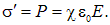
Using relation (3.3) between the field strength E ' of the polarization charges and the total field E

we find the relation between the dielectric permittivity and the dielectric susceptibility
|
|
(3.23) |
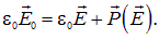
In the general case the polarization vector P is not parallel to the strength vector of the total field E: in anisotropic dielectrics the polarization vector may rotate relative to the field strength. However, we can always write the relation
|
|
|
(3.24) |
|
The quantity
is called the electric displacement vector (electric induction vector). |
In the particular case of a linear dependence of the polarization on the field strength

the electric displacement vector equals
|
|
(3.26) |
where  — is the dielectric permittivity of the medium. The relation

holds for isotropic dielectrics. In the general case the vector D is not parallel to E. The field of the vector D can be represented graphically by lines of electric displacement, which are defined in the same way as the lines of electric field strength (Figs. 3.23 and 3.24).
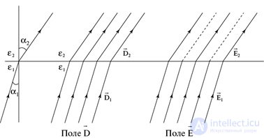

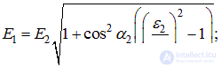
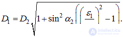
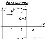
Fig. 3.23. Conditions at a plane boundary between two dielectrics for the field strength and the electric displacement
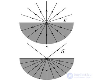
Fig. 3.24. Lines of field strength and electric displacement of the electric field
from a point charge located at the interface between two dielectrics
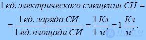
|
In SI the unit of measurement of electric displacement is:
|
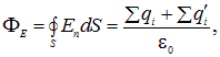
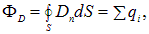
Let us apply the Ostrogradsky–Gauss theorem to the electric field in a dielectric. The flux of the strength vector through a closed surface is proportional to the algebraic sum of the charges (free and polarization) located inside the volume bounded by this surface
|
|
(3.27) |
where qi — are the free, and q 'i — the polarization charges. This expression is inconvenient, since it includes polarization charges, which, in turn, depend on the strength of the electric field at the given point of the dielectric.
Let us now consider the flux of the electric displacement vector
|
|
(3.28) |
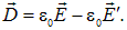
Since the strength of the field of the polarization charges can be written as

then
|
|
(3.29) |
Consequently,

from which
|
|
(3.30) |
where qi — are the free charges. It should be emphasized that the lines of the vector D can begin and end on free charges, but not on polarization charges.
Attention should be drawn to the absence, in the right-hand side, of the factor  , which is present in the analogous expression for the flux of the strength vector in vacuum.
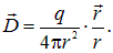
From the Ostrogradsky–Gauss theorem for a point charge q inside a dielectric it follows that
|
|
(3.31) |
The vector D does not determine the force acting on a charge from the external electric field. The force characteristic, as before, is  , that is
  . For a linear dependence of
  on
on  , to calculate the force one should use the relation

from which
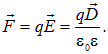
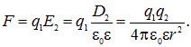
Let us now obtain Coulomb's law for such dielectrics. A free charge q2 creates in the dielectric an electric displacement

from which follows the expression for the force of interaction with another free charge q1
|
|
(3.32) |
Accordingly, the expression for the potential created by a free charge q changes
|
|
(3.33) |
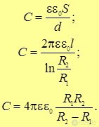
and, as a consequence, so do the formulas for the work of moving a free charge in a field and for the energy of interaction of free charges. We note that, compared with the analogous formulas for systems of charges in vacuum, for dielectrics one must make the substitution  Since the expressions given served as the primary source for all the other relations we derived for vacuum, we immediately obtain, for example, the expressions for the capacitances of a parallel-plate (2.12), cylindrical (2.14), and spherical (2.17) capacitor filled with a homogeneous dielectric (Figs. 3.25, 3.26, 3.27, 3.28)
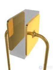
Fig. 3.25. The basis of a capacitor's construction — two conducting plates with a dielectric between them
|
|
(3.34) |
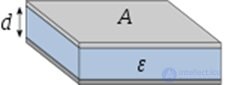
Fig. 3.26. A parallel-plate capacitor with a dielectric
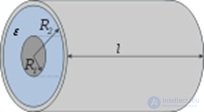
Fig. 3.27. A cylindrical capacitor with a dielectric
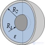
Fig. 3.28. A spherical capacitor with a dielectric
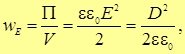
For the energy density of the electric field (2.57) we can now write the expression
|
|
(3.35) |
which can be represented in vector form:
|
|
(3.36) |

















Comments