Schematic diagram.
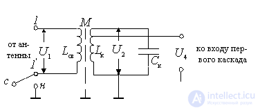
Figure 8.1.
Parallel contour  performing frequency selectivity, communicating with the antenna using a coupling coil
  . An antenna or feeder can be asymmetrical or symmetrical. With an unbalanced antenna, the antenna itself or the potential wire of the feeder is connected to terminal 1, while terminal 1 'is connected to the housing. In the case of a balanced antenna or feeder, the receiver input must be balanced. For this purpose, the clamp 1 'is disconnected from the housing and the input circuit is made as strictly symmetrical as possible. For this purpose, an electrostatic screen is sometimes placed between the coils, special methods of winding, etc. are used.
To ensure the necessary degree of connection with the antenna-feeder system, the mutual induction coefficient M and the inductance of the coupling coil are chosen in a certain way. . The value of

should be constructively feasible.
The equivalent circuit of the input device.

Figure 8.2.
The antenna in this diagram is presented in the form of an emf generator.  with active internal resistance
  . This scheme is a special case of the general equivalent circuit of the input circuit with a transformer coupling with
Scheme parameters:
 ;
;  ,
,
Where  ,
,  .
.
If the antenna is matched to the feeder, then
 ,
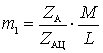
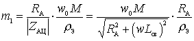
,  . The connection with the antenna, as usual, is estimated by the magnitude of the transformation ratio. At the last lesson for the circuit with a transformer connection when working with an unconfigured antenna was obtained:
 .
.
Then
 .
.
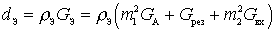
Input device parameters.
Resonance gain:
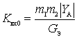 ,
,
as with tuned antenna  then
then
 ,
,
Where  - active conductivity of the antenna;
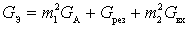 - equivalent circuit conductivity.
The resulting attenuation in the circuit
 ,
,
When working with tuned antennas at the input, the matching mode is usually carried out at specified fixed frequencies or at the middle frequency of the subband. On the matching frequency  has a maximum value. At all other frequencies, given the frequency dependence of the coefficient
  , and
, and  and
and  , the transmission coefficient, the resulting attenuation, the bandwidth and the noise coefficient will differ from the values in the matching mode.

Comments