Let's open the generalized equivalent circuit considered in the first question, presenting its parameters in the form of active and reactive elements. Conductivity  introduced by the antenna contains as active
  and reactive
  component. The conductivity of a parallel circuit is represented in the form of its main elements: inductance L , capacitance C and conductivity G. The input of the first cascade, characterized by recalculated conductivity
  , also present in the form of active
  and capacitive
  constituents. The corresponding equivalent circuit is shown in the figure.
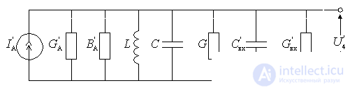
Figure 6.2.
Resulting inductance  input circuit consists of the inductance of the coil circuit, as well as the inductance
  introduced by the antenna:
 .
.
Output Capacitance Capacity:
 .
.
Where  - capacity introduced by the antenna side;
С - contour capacity;
С L - parasitic capacitance of the inductor;
C M - installation capacity;
C P - capacity trimming circuit;  - capacity introduced by the input of the first cascade.
Characteristic resistance of the circuit with the specified parameters
 .
.
Resulting Active Conductivity
 .
.
Taking into account the above values, an equivalent circuit is obtained;
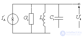
Figure 6.3.

Comments