General information.
In amplifiers, feedback is possible through the power supply circuits, through the connecting circuits of the amplifier, through the conductivity of the internal feedback of the amplifying device. The first two types of feedback, in principle, can be eliminated by rational design of the circuit and amplifier design.
Consider the influence of the internal OS. Internal OS in the amplifier due to reverse mutual conductivity  . In lamp amplifiers with a common cathode, it is determined by the passage capacity of the lamp
  . In a bipolar transistor amplifier
  is a complex value

Where
 ;
; 
Equivalent amplifier circuit taking into account the influence of the internal OS and its parameters.
To analyze the effect of the internal OS, we consider an amplifier circuit with an input circuit. In this diagram, for clarity, the elements of the conductivity of the internal OS  and
and  shown as if rendered outside the active element.
Through the internal OS, the parasitic effects of the output circuit of the amplifier on the input are created. We estimate this impact.
Feedback conductivity  creates a current at the input of the amplifier
  which is equivalent to the occurrence of component input conductance
  due to internal feedback. This component is called the input dynamic conductivity.
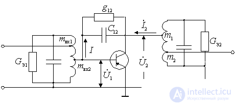
Figure 10.1.
From the expression for  previously received

we get
 .
.
Substitute the parameters in this expression
 and
and  ,
,
then we get
 ,
,
Where  - work argument
  .
.
 ;
;  .
.
We apply the Euler formula to the expression for  :
:
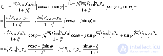
Applying the Euler formula to  after the corresponding transformations we get
 .
.
From the obtained expression it is clear that the input dynamic conductivity contains active and reactive components. Each of them can be decomposed into two components, which depend differently on the detuning of the output circuit:
 ;
;  ;
;
 ;
;
 ;
;
 ;
;
 .
.
We show the nature of dependencies.  :
:

Figure 10.2.
These components of the input dynamic conductivity shunt the input circuit, which leads to a change in the shape of the resonance curve.
Analysis of the influence of the internal OS in a tube amplifier and an amplifier on a field-effect transistor.
In a tube amplifier and a field-effect transistor amplifier
 ,
,  ,
,  the slope S is a real value
 , so
, so  ;
;  and there are only two conductivities due to the presence of
 ,
,
 .
.
Consider the effect of these conductivities on the shape of the resonant curve of the circuit at the input of the amplifier. We will assume that it is tuned to approximately the same frequency as the output circuit. If all components of the input dynamic conductivity did not depend on the frequency, then the resonant curve of the input circuit would have the form shown in the figure by a solid line.
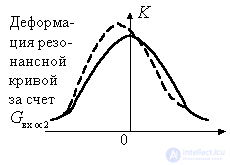
Figure 10.3.
In reality  and
and  vary with frequency. At frequencies below the resonant conductivity
  negative and therefore causes a boost in gain. This can be explained as follows. At frequencies below the resonant output circuit has an inductive impedance.

Figure 10.4.
Therefore stress  ahead of the current
  at an angle close to 90 °. This voltage causes current to flow.
  through capacity
  , leading the voltage by another 90 °. Since the current
  in-phase voltage
  and current
  phase shift will be equal to 180 °, which is equivalent to negative input conductance. It compensates for the loss of the input circuit, causing an increase in voltage, i.e. A positive OS occurs in the amplifier.
At frequencies above the resonant conductivity  is positive. It introduces additional losses into the input circuit, leading to a decrease in the gain, i.e. There is a negative OS.
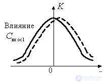
Figure 10.5
Influence  the shape of the resonant curve of the input circuit is manifested in the fact that with decreasing frequency the total capacitance of the circuit will decrease, and its resonant frequency will increase. The actual detuning will be greater than the one for which the frequency has been reduced. Therefore, the gain will decrease more sharply (dashed line to the left of the ordinate axis). With increasing frequency, the total capacitance of the circuit will decrease and the resonant frequency of the circuit will increase. The contour will partially adjust to the changing frequency. As a result, the actual detuning decreases, the gain is greater than in the absence of feedback (the dashed line to the right of the ordinate axis).
Analysis of the influence of the internal OS in the amplifier on a bipolar transistor. In a bipolar transistor amplifier the effect of capacitance  leads to similar changes in the shape of the resonant curve of the input circuit. However, due to the complexity of the direct and inverse mutual conductivities
  and
and  all four components of the input dynamic conductivity take place:
  ;
;  ;
;  ;
;  .
.
The nature of the influence of conductance  and
and  same as in field-effect transistors and lamps.
Consider the effect of conductance.  and
and  on the shape of the resonant curve of the input circuit.
Changes  with a frequency, it is as if partially adjusting the input circuit to the changing frequency, i.e. extend the top of the resonance curve. Valid at resonance
  equals zero. With decreasing frequency
  increases, the resonant frequency decreases, and the actual detuning of the circuit relative to the resonance decreases. With increasing frequency
  is negative. The total capacitance of the circuit decreases, the resonance frequency increases, which leads to a decrease in the actual detuning and, accordingly, to an increase in the gain. With a large enough misalignment
  decreases and ceases to influence the shape of the resonant contour curve.
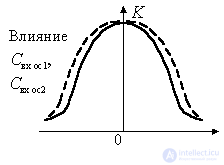
Figure 10.6.
Conductivity  decreases when the frequency deviates from the resonant in both directions. In this case, the Q-factor of the input circuit increases, and the gain on the right and left of the resonance increases. The top of the resonance curve expands, the squareness improves. Thus, the analysis showed that the presence of internal feedback in the amplifier leads to deformation of the resonant characteristics of the input circuit and may even cause self-excitation of the amplifier due to the negative nature of the conductivity.
  .
.


Comments
To leave a comment
Devices for the reception and processing of radio signals, Transmission, reception and processing of signals
Terms: Devices for the reception and processing of radio signals, Transmission, reception and processing of signals