Lecture
A block diagram of a television system (excluding the transmission of sound accompaniment of television programs) is shown in Figure 9.3.
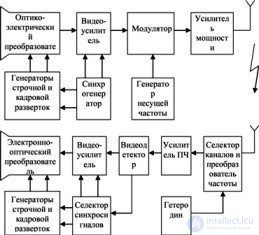
Fig. 9.3 Block diagram of the black-and-white image transmission system
The signal at the output of the video amplifier, in addition to the image signal, contains personnel and horizontal sync signals, and signals for blanking reverse frame and horizontal scanning and is called a full television signal. The full television signal is fed to the modulator, the second input of which receives the colo *** of the carrier frequency from the output of the carrier frequency generator. The modulated colo *** of the carrier frequency from the modulator output is fed to the transmitting antenna after the necessary amplification in the power amplifier.
The emitted transmitting antenna signal reaches the receiving antenna and, together with signals from other television channels and induced interference, is fed to the input of the television receiver. The channel selector and the frequency converter use a local oscillator to select the desired receive channel and transfer the spectrum of the received signal to a fixed intermediate frequency at which the main amplification of the signals occurs.
The amplified intermediate frequency signal is fed to a video detector, at the output of which a combined image signal and synchronization signals and reverse sweep cancellation signals are allocated. The signals of the video detector are fed to the electron-optical converter and the selector of clock signals. The sync signal selector allocates vertical and horizontal sync signals to control the operation of the vertical and horizontal generators of the receiver of television signals. Frame and line scan generators generate signals that provide the formation of the image scan on the television receiver screen.
The electro-optical converter converts an electrical signal into a brightness mark of one image element. As a result of the joint operation of the electro-optical converter and the device for the formation of a scan, a black and white image will be formed on the screen of the television receiver corresponding to the illumination (brightness) of the original at the input of the transmitting device of the communication system.
Real television broadcasting systems in addition to transmitting image signals also provide sound accompaniment for television programs. In addition, modern television systems provide additional service functions.
The structure of a complete television signal in the interval of one line during the forward course of a frame scan is shown in Figure 9.4.
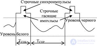
Fig. 9.4 Full TV signal on the active line interval
On the time interval TSHR corresponding to the direct course of the line scan, the image brightness signal is transmitted. The magnitude of the signal at each time point depends on the illumination (brightness) of the corresponding decomposition element and its reflectivity. The signal level at the output of the optical-electrical converter, depending on the illumination of the object, can vary from the so-called black level to the white level. For the signal shown in Figure 9.4, it is assumed that the most illuminated (bright) element of the image decomposition corresponds to the smallest value of the signal at the output of the optical-electrical converter, and the darkest element corresponds to the maximum value of the signal. Such a dependence of the level of an electrical signal at the output of an optical-electric converter on the intensity of an optical signal (brightness, luminance) is called negative coding of the signal brightness.
At the time interval corresponding to the reverse run of the line scan, a line quenching pulse is added to the image signal. The magnitude of the television signal at this interval, regardless of the brightness of the object, takes on a value greater than the black level. This is done so that not a single element of the screen is “highlighted” by random interference during the horizontal flyback.
During the reverse sweep, the horizontal sync signal is also transmitted. The level of these signals is in the so-called area "blacker than black", so these signals do not affect the formation of the image signal.
The principle of formation of personnel horizontal pulses and personnel quenching pulses is the same as the corresponding horizontal pulses. During the return stroke of the frame sweep, a personnel quenching pulse is formed, its level is the same as the level of the horizontal quenching pulse, and the duration corresponds to the duration of the reverse sweep of the personnel sweep. Frame sync pulse is designed to ensure synchronization of frame sweeps of the transmitter and receiver.
The principle of formation of personnel horizontal pulses and personnel quenching pulses is the same as the corresponding horizontal pulses. During the return stroke of the frame sweep, a personnel quenching pulse is formed, its level is the same as the level of the horizontal quenching pulse, and the duration corresponds to the duration of the reverse sweep of the personnel sweep.
Frame sync pulses are designed to ensure synchronism in the work of personnel sweeps of the transmitter and receiver. In order to separate the personnel and horizontal sync pulses in the television receiver, the duration of the digital sync pulses was chosen to be significantly longer than the horizontal sync pulses.
Since the frame and line sync pulses have the same level, during frame retraction, the line sync pulses overlap with frame sync pulses and the line sync information in the full television signal can be lost. During the absence of horizontal sync pulses, horizontal sync synchronism can be disrupted. To eliminate this situation, special so-called tie-in pulses form in the frame sync pulse. Synchronization line scan at the stage of formation of the frame sync pulse is performed on the trailing edge of the inset pulse (outside the frame sync pulse sync line scan is performed on the leading edge of the horizontal sync pulses).
The structure of a full television signal in the frame of a personnel extinguishing impulse is shown in Figure 9.5.
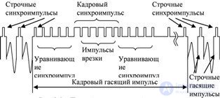
Fig. 9.5 Full television signal during frame reversal
With interlaced scanning, frame sync pulses begin at the beginning of the line in the odd half-frame and from the middle of the line in the even-half frame. To equalize the operation of the sync pulse allocation circuit for even and odd half-frames, the pulse repetition rate of the tie-in is made twice as large as the horizontal sync pulse. In addition, immediately before the frame sync pulse and immediately after it, 5 pulses are injected with a repetition rate equal to twice the repetition frequency of the horizontal sync pulses, called leveling pulses.

Comments
To leave a comment
Devices for the reception and processing of radio signals, Transmission, reception and processing of signals
Terms: Devices for the reception and processing of radio signals, Transmission, reception and processing of signals