Lecture
We determined that, to increase the sensitivity of the detector receiver, the principle of direct frequency conversion can be applied. However, in this case, a part of the output oscillation (a component of the spectrum with a doubled signal frequency) has to be suppressed. This means that the power of the useful signal at the output of the multiplier (mixer) will be two times less than the signal power at the input. In other words, the mixer gain cannot exceed –3 dB. In real-world circuits, the situation is worse due to losses in the multiplier elements. The active multiplier (multiplier with amplification) does not change the situation at the root, since it amplifies not only the signal, but also the noise, which means that the noise figure will, at best, remain exactly the same.
To increase the sensitivity of the radio receiver (reducing the noise figure of the receiver), a low-noise high-frequency amplifier (UHF) is placed between the input of the synchronous detector and the output of the input device of the receiver. Its gain is calculated using the following formula:
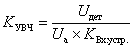
where U det - the voltage at the input of the synchronous (quadrature) detector;
U and - the voltage at the output of the antenna;
K in. devices - the transfer coefficient of the input device.
The block diagram of a direct gain receiver with a quadrature detector capable of receiving a signal with any kind of modulation is shown in Figure 1.
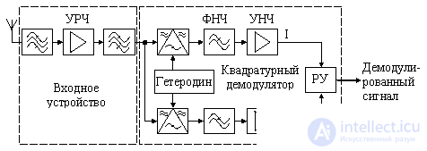
Figure 1. Block diagram of a direct gain radio receiver
The use of a high-frequency amplifier allows you to raise the sensitivity of the receiver to several tens of microvolts. However, at the same time, it is this amplifier cascade that will mainly determine the level of intermodulation distortion. It should be noted here that the circuit shown in Figure 1 can be defined both as a direct amplification circuit and as a direct conversion circuit. It all depends on which cascade will determine the selectivity of the adjacent channel and where the main gain will be concentrated.
If, in the circuit shown in Fig. 1, the main gain is determined by a low-frequency amplifier, and the selectivity over the adjacent channel is provided by the low-pass filter at the output of the quadrature detector, then this circuit is considered as a direct conversion receiver. The choice of frequency parameters of the blocks of the circuit is illustrated in Figure 2.
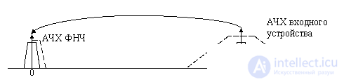
Figure 2. Requirements for direct conversion receiver filter characteristics
If the main selectivity of a radio receiver over the adjacent channel and its main gain, is concentrated to a quadrature detector, then it is considered as a receiver of direct amplification. In this case, the frequency parameters of the radio receiver circuit are selected in accordance with Figure 3.
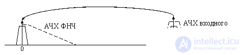
Figure 3. Requirements for Direct Gain Receiver Filter Characteristics
Since, in this case, all receiver parameters are determined by the input device and are practically independent of the parameters of the quadrature detector, the direct gain receiver circuit can be represented as shown in Figure 4.

Figure 4. Block diagram of the direct gain receiver
The requirements for a low-frequency quadrature detector in this circuit are significantly reduced compared with the direct conversion circuit. Here, the low-pass filter should suppress the components of the doubled frequency of the received radio signal and not distort the useful signal.
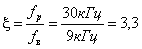
In the worst case, the frequency offset can be determined as follows:
in this case, the calculation of the low-frequency filter (LPF) is performed in the same way as we considered in the chapter on the direct conversion receiver.
The frequency parameters of the radio path of the direct gain receiver are determined by Figure 5. This figure shows the spectrum of the working channel and the spectra of two adjacent radio channels. The band-pass filter of the input device of the direct gain receiver must not distort the useful signal and at the same time suppress the spectrum of adjacent channels.
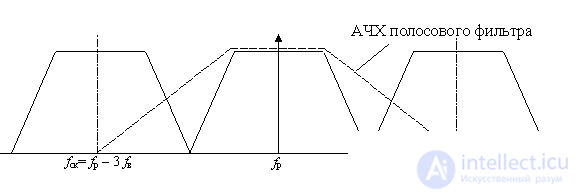
Figure 5. Frequency parameters of the radio path of a direct gain receiver
It is known that the calculation of the bandpass filter is carried out through the calculation of the low-pass filter of the prototype filter, which is calculated in the same way as in the case of a direct conversion receiver. Using these results, you can determine that a bandpass filter of at least seventh order is required.
Now we will determine to what frequency it will be possible to apply the direct amplification scheme. It is known that the constructive quality factor of the circuit is difficult to get more than 200. Given that the Butterworth filter has the quality factor of the circuit with the highest quality factor different from the quality factor of the circuit with the smallest quality factor five times, we will use the quality factor to determine the maximum frequency:
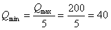
The quality factor of the contour is determined by the following formula:

Then the maximum operating frequency for a communication system using signals with a 9 kHz bandwidth can be determined from the following expression:

This means that the scope of direct-gain receivers is limited to the long-wavelength range. Radio amateurs use direct amplification receivers in the mid-wave range, but this is achieved by reducing the suppression of the adjacent channel. For professional communication systems this is unacceptable.
The gain of a radio frequency amplifier in a direct amplification scheme is limited by out-of-band interference that can enter its input and cause overload. Receivers collected by direct amplification are usually designed to receive one specific frequency. This is due to the complexity of developing a tunable bandpass filter. The frequency received by the direct gain receiver is determined by the tuning frequency of the input device filter. Considering that this scheme is mainly used in remote control systems, and they operate in the microwave range, then surface acoustic wave filters are usually used as frequency-selective circuits of the input device.

Comments