Lecture
In the diode converter considered earlier, the output contains not only conversion products, but also a local oscillator signal. An ideal multiplier at the output should not have this component in the output signal spectrum. In order to remove this component of the output signal is usually used push-pull circuit, called a balanced mixer. Diagram of a diode balanced mixer is shown in Figure 1.
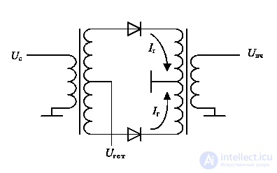
Figure 1. Diagram of a diode balanced mixer.
In this scheme, the currents caused by the local oscillator ( I g) flow along the windings of the input and output transformers in opposite directions, so they compensate each other at the input and output of the mixer circuit. As a result, the output current caused by the local oscillator voltage is significantly reduced. In exactly the same way, the heterodyne current is compensated in the input circuit of the mixer. Together with the heterodyne current in the output signal of a balanced mixer, all its odd harmonics are simultaneously suppressed.
Unfortunately, it is not possible to fully compensate the heterodyne current at the output of the balanced mixer because of the inaccuracy of the amplitude of oscillation of the local oscillator in each of the arms of the diode mixer. In addition, these currents are slightly different in phase, but attenuating its level by 40 dB can significantly improve the characteristics of the frequency converter and bring them closer to the characteristics of an ideal signal multiplier.
Figure 2 shows a family of graphs that allow one to estimate the depth of suppression of the local oscillator signal as a function of the imbalance of the arms of the balanced mixer in amplitude and phase.
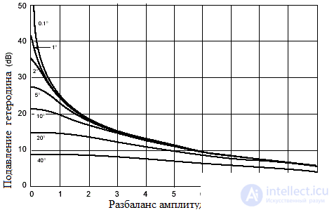
Figure 2 The family of dependences of the suppression of the local oscillator signal from the imbalance of the arms of the balanced mixer in amplitude and phase
The signal spectrum at the output of the diode balanced mixer is shown in Figure 3.
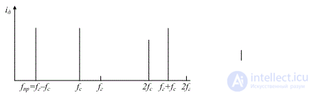
Figure 3 The signal spectrum at the output of a balanced diode mixer
In the diode balanced frequency converter circuit shown in Figure 1, there are two transformers with a tap from the midpoint. Such transformers are difficult to make constructively, therefore, in some cases, a balanced frequency converter circuit is used, in which an ordinary transformer is used at the output, which simply leads the output impedance of the frequency converter to a standard value of 50 ohms. A similar scheme of a balanced frequency mixer is shown in Figure 4.
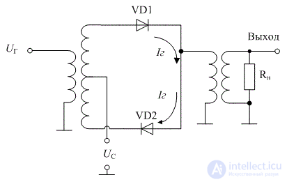
Figure 4 Diagram of a diode balanced mixer with a single transformer with a tap
In this scheme, the heterodyne current is closed in the ring of the balanced mixer and practically does not branch into the load circuit. The input and output of this circuit is asymmetrical, and transformers allow the standard impedance of the signal source and load (equal to 50 Ohms) to lead to the resistance of the diode converter, at which the maximum transmission coefficient is achieved.
Currently, mixers are often performed in the form of ready-made integrated circuits. This solution allows you to do a minimum of external mounted elements. The best quality parameters of the microcircuit are obtained using a polycore substrate, on which unpackaged elements or elements intended for surface mounting (smd elements) are mounted. Figure 5 shows a photograph of the mixing chip with the lid removed.
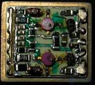
Figure 5. The design of the balanced mixer field-effect transistors.

Comments
To leave a comment
Devices for the reception and processing of radio signals, Transmission, reception and processing of signals
Terms: Devices for the reception and processing of radio signals, Transmission, reception and processing of signals