Lecture
The main disadvantage of a direct gain receiver is the complexity of tuning from one frequency to another. It is practically impossible to perform a filter with stable parameters when it is rearranged in the frequency range.
When amplifying a high-frequency signal, certain difficulties also arise. The higher the frequency of the received signal, the more difficult it is to perform a high-frequency amplifier. Its broadband also leads to certain difficulties. Naturally, with the development of microelectronics, the price of these costs gradually decreases, but at the same time more and more high-frequency bands are being mastered.
As a second and, perhaps, the main disadvantage of a direct gain receiver is the need to build a tunable narrowband filter tuned to the working signal. The requirements for this filter are inconsistent. On the one hand, this filter should attenuate the adjacent receiving channel, and on the other hand, not distort the received signal. As a result, if necessary frequency tuning is required to change the relative bandwidth of the filter.

Where  - frequency band of the useful signal
f ps - the carrier frequency of the useful signal
As the center frequency of the filter is increased, in order to maintain the same absolute frequency band, it is necessary to simultaneously reduce the relative bandwidth of the filter. This is achieved by increasing the quality factor of the circuits included in the filter. Considering that it is necessary to strictly monitor the ratio of the Q-factors of these circuits to each other, as well as the fact that the higher the frequency, the harder it is to realize the high quality of the resonant circuit, the task becomes almost impossible.
Even in the case when the receiver is designed for one fixed frequency, it is very difficult to provide the parameters of a narrow-band filter. At 450 MHz, it is very difficult (almost impossible) to ensure a filter bandwidth of 10 kHz with a stopband of 25 kHz. In this case, the minimum quality factor is required:
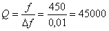
But this is for the first order filter! And you need at least an 8th order filter. Naturally, the quality factor of an electoral circuit equal to several hundred thousand units cannot be technically completed!
In order to solve this problem, they began to divide the problem into two stages - restructuring over a range of frequencies, and ensuring selectivity over the adjacent channel. For tuning the frequency range, they began to use the transfer of the spectrum to a certain (usually quite low) intermediate frequency. The transfer of the spectrum of received frequencies is carried out using the following trigonometric transformation:
then the voltage at the output of the multiplier, which is often called a mixer, will be recorded:

A narrowband filter at the output of the multiplier easily suppresses one of these components. The remaining frequency component of the output signal is called the intermediate frequency. A radio receiver operating on this principle is called superheterodyne. Usually at the mixer output of such a radio receiver, a difference component is allocated. In this case, a signal is generated at the input of the intermediate frequency amplifier (IFA), with a frequency of:

It turns out that with the help of a mixer you can easily move the input signal spectrum in frequency by changing the frequency of the local oscillator - the local oscillator.
The process of moving the frequency of the input signal to the intermediate frequency in the superheterodyne is illustrated in Figure 1.
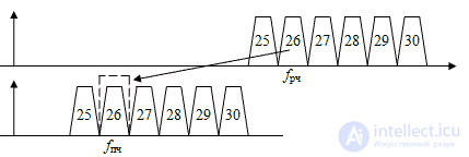
Figure 1 Transfer spectrum of the received signal at an intermediate frequency.
In this figure, the trapezoid shows the spectrum of the signal transmitted in the radio channel. The number depicted in the trapezoid means the number of the radio channel adopted in the mobile radio communication system.
Receivers made according to the scheme with the transfer of the radio frequency band to an intermediate frequency, are called superheterodyne or superheterodyne receivers. If the transfer is carried out at zero frequency, then such a receiver will already be called a direct conversion receiver. The structure of a radio receiver built according to the superheterodyne scheme with a single frequency conversion is shown in Figure 2.

Figure 2. Superheterodyne radio receiver block diagram
In this scheme, the local oscillator performs tuning in the frequency range, so it is often performed as a frequency synthesizer that can be tuned to a number of fixed frequencies and has frequency stability corresponding to a crystal oscillator or, in particularly important cases, an atomic frequency standard.
To reduce the requirements for the filter of primary selectivity, the intermediate frequency path is chosen sufficiently low-frequency. This allows you to provide a significant relative detuning of the frequency of the adjacent channel with respect to the band of the received signal.
The fact that the intermediate frequency of the superheterodyne receiver is fixed allows the use of a quartz, electromechanical or piezoelectric filter as an intermediate frequency filter. This ensures high electrical characteristics of the filter of primary selectivity and high stability of characteristics in time and in the range of temperatures. In addition, such filters are currently high-tech, which allows to reduce the cost and reduce the size of the receiver as a whole.
Unfortunately, the intermediate frequency can be formed using two equations. In this case, the result can not be distinguished from each other:

This leads to the fact that a superheterodyne receiver can simultaneously receive two frequency channels simultaneously, spaced by 2 f bees from each other. One of these channels is called the working channel, and the other is the mirror channel. The situation described is illustrated in Figure 3.
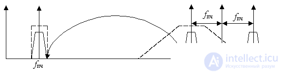
Figure 3 The formation of a mirror channel in a superheterodyne receiver
The main way to get rid of the mirror channel is to suppress its signal in the input circuit of the radio receiver, in other words, the suppression of the mirror channel depends on the selectivity of the input circuit of the superheterodyne and the relative detuning of the frequency of the mirror channel:

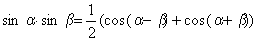
Additional suppression of the mirror channel can be provided in the mixer with the suppression of the mirror channel. This frequency converter implements one of the following trigonometric formulas:


In some cases, this circuit solution may reduce the specific value of the intermediate frequency, increase the depth of suppression of the specular channel, or extend the range of frequencies in which the superheterodyne receiver circuit with a single frequency conversion can be applied.
The selectivity requirements of the bandpass filter of the input circuit of a super heterodyne receiver are significantly lower than the requirements for a bandpass filter of a direct gain receiver. This is due to the fact that the mirror channel is rebuilt from the received frequency much further than the adjacent channel. The higher the value of the intermediate frequency is chosen, the lower will be the requirements for the bandpass filter of the input circuit. This will increase the requirements for an intermediate frequency bandpass filter. The specific choice of the intermediate frequency value allows you to optimize the requirements for both the intermediate frequency path and the requirements for the input frequency.
When calculating the structural scheme it is very important to correctly distribute the gains of each block. As already discussed above, the sensitivity of the receiver is determined by the noise level of each of the stages, however, the first stage of the receiver has the greatest influence on this parameter. In order for subsequent cascades not to have a significant effect on the sensitivity of the receiver, you can raise the gain of the first cascade, but this will lead to an increase in intermodulation distortion, therefore in most cases it is necessary to limit compensation for losses in subsequent cascades. An example of the distribution of the gain over the cascades of the superheterodyne receiver is shown in Figure 4.
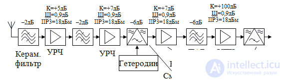
Figure 4 Example of signal level distribution in the superheterodyne receiver block diagram
Development of the structural scheme is a crucial stage in the design of a radio receiver. In each case, it is necessary to take into account the characteristics of the received signal and the requirements for the parameters of the device as a whole.
We consider the receiver circuit of digital modulation methods, therefore, when developing a superheterodyne receiver of digital modulation types, one should take into account the peculiarities of transferring the useful signal to the intermediate frequency. The useful information of a digital signal is usually contained in the relative change in the phase of the carrier wave, but it leads to a corresponding frequency increment:

In this case, a positive phase increment will increase the frequency of the received signal, and a negative one will decrease. When converting a frequency in a superheterodyne receiver, the frequency increment can, as it does not change - when converting , and become the opposite - when converting . This effect is illustrated by Figure 3. It shows by an arrow that the upper and lower side frequencies of the received signal are shifted by places when transferred to an intermediate frequency. In this case, the sign of the phase increment becomes opposite and the transmitted message is distorted. Recovery of the transmitted message at the output of such a radio becomes impossible.
The considered phenomenon can be taken into account at the output of the superheterodyne receiver in a quadrature detector. If we swap the quadrature signals I and Q, then the rotation of the frequency vector at the output of the quadrature detector is reversed. The transmitted message will now be received correctly.

Comments
To leave a comment
Devices for the reception and processing of radio signals, Transmission, reception and processing of signals
Terms: Devices for the reception and processing of radio signals, Transmission, reception and processing of signals