Lecture
General information.
In radio signal amplifiers, there are mainly two options for switching the amplifier device in stages on:
a) bipolar transistors:
- with a common emitter (OE);
- with a common base (OB);
b) field effect transistors:
- with a common source (OI);
- with a common gate (OZ);
c) lamps:
- with common cathode (OK);
- with a common grid (OS).
Amplifiers with a common emitter (source, cathode) in the range of meter and longer wavelengths make it possible to obtain the greatest gain in power.
Amplifiers with a common base (gate, grid) are more resistant to self-excitation, and therefore are often used in the decimeter and centimeter wavelengths. The principles of construction and analysis of resonant amplifiers are identical for different types of amplifying devices and options for their inclusion. Therefore, in the further analysis, we will mainly consider schemes with OE (OI, OK). According to the method of connection of the circuit with the active elements, there are schemes with direct, autotransformer and transformer coupling.
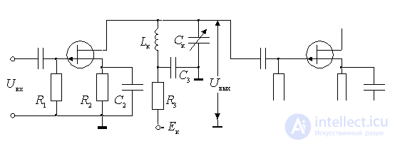
Resonant field-effect transistor amplifier. The difference between this amplifier and the resistor is that a parallel circuit *** is connected to the drain circuit.

Figure 9.1.
 - power supply drain;
 - resonant load amplifier;
 - decoupling filter supply chain,
  is selected from the condition
  - at the same time, the resonant frequency of the circuit will be practically determined by the parameters
  .
.
 - a resistor providing a predetermined bias voltage at the gate;
 - a resistor used to transfer the bias voltage to the gate;
 - eliminates the negative operating system for alternating current;
 - separation.
In the scheme applied sequential power flow through decoupling filter  and inductance
  .
.
Often used autotransformer drain connection to the circuit, allowing to increase the stability of the amplifier.
Resonant amplifier on a bipolar transistor.
In bipolar transistors, a partial connection to the circuit of the amplifying device and the load is used. This allows you to reduce the shunting circuit relatively small input and output resistances of the transistors. In addition, as noted above, the incomplete connection of the circuit can improve the stability of the amplifier.
Consider the autotransformer and transformer communication schemes.
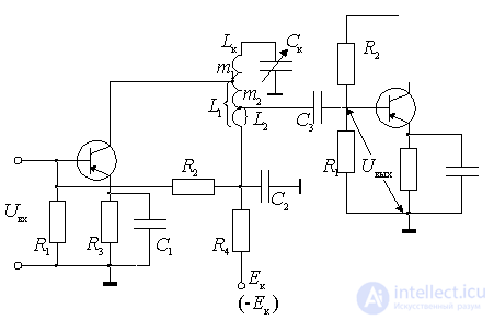
Circuit with a double autotransformer coupling circuit.

Figure 9.2.
 - a divider providing the working point of the transistor;
 - a resistor that provides temperature stabilization of the operating point at the expense of direct current feedback;
 - eliminates the operating system for alternating current;
 - decoupling filter supply chain;
 - resonant load amplifier;
 - separation capacitor, which prevents the supply voltage of the collector to the base circuit of the second transistor.
In this scheme, the amplifier transistor is autotransformer connected to the circuit with a coefficient
 .
.
The input of the next cascade is autotransformer connected to the circuit with the switching coefficient
 .
.
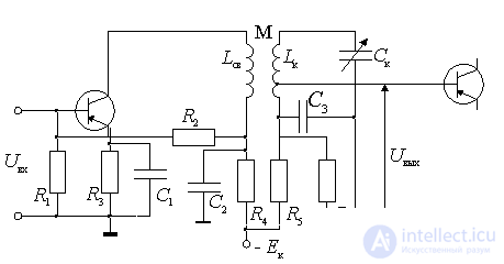
In the second circuit, the circuit has a transformer connection with the collector of the transistor of this cascade and an autotransformer with the input of the next. Transformer connection is structurally more convenient (more flexible). Other design options are possible.

Figure 9.3.
Common to all schemes is a double partial inclusion of the circuit. Full inclusion can be considered as a special case when the inclusion coefficients are equal to 1. Therefore, for analysis, you can use one generalized equivalent circuit of the amplifier.
Comments
To leave a comment
Devices for the reception and processing of radio signals, Transmission, reception and processing of signals
Terms: Devices for the reception and processing of radio signals, Transmission, reception and processing of signals