Schematic diagram.
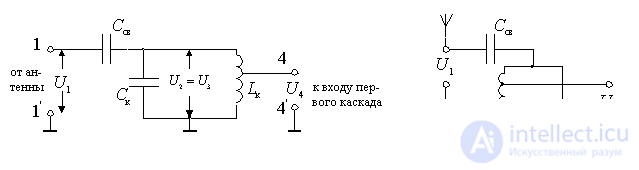
Figure 7.6.
A contour is used as a frequency selection system.  reconfigured by changing capacitance or inductance. The antenna is connected to the circuit using a capacitor.
  .
.
and contour capacities  determines the transmission coefficient of the input device and the degree of influence of the antenna parameters on the bandwidth and frequency shift of the loop tuning. It should be borne in mind that when setting the input circuit with a change in capacitance the magnitude of the connection with the antenna also changes.
Comments
To leave a comment
Devices for the reception and processing of radio signals, Transmission, reception and processing of signals
Terms: Devices for the reception and processing of radio signals, Transmission, reception and processing of signals