Lecture
Television refers to the transmission of optical images using technical means at a distance. The parameters of communication devices that transmit television signals must be consistent with the characteristics of the organs of human vision.
The source of optical information for humans is visible light in the wavelength range of 380 ... 760 nm, emitted or reflected by various physical bodies. The receiver of this information is the human eye. The optical system of the eye using a transparent lens shaped like a biconvex lens and muscles that control the radius of curvature of the lens converts the light flux from the object and focuses it into an inverted image on the back of the eyeball called the retina.
The retina consists of many nerve endings of two kinds. About 7 million nerve endings, shaped like cones, are located mostly within a small area opposite the lens. This small area of the retina is characterized by the best vision and is called the yellow spot. Cones are able to distinguish both the intensity of a light wave that carries information about the illumination of an object or the brightness of its radiation, and the length of this wave that carries information about the color of an object. Around the yellow spot are more than 100 million nerve endings, shaped like sticks. The rods are more sensitive receptors of the intensity of optical fluxes, that is, they are able to detect weaker light signals, but the rods are not able to distinguish the length of the light wave, that is, they cannot distinguish the colors of objects.
The photosensitive elements of the eye transform the energy of light waves into signals of the human nervous system transmitted to the visual centers of the brain, where the incoming information is processed. As a result of the processing of impulses from many millions of nerve endings, an integral image of the object is formed: brightness, color, geometrical dimensions, etc.
The system of transmitting optical information over short distances can be implemented using optical fibers. Fiber optic fibers are transparent to light, bundled and capable of transmitting optical signals through internal reflection, even along a curved path. If on one end of a bundle of such fibers to design an image of an object, then this image can be transferred as a sum of individual image elements transmitted by each of the fibers.
Each of the elements of such a divided image can be transmitted using electrical signals (with a preliminary conversion of an optical image into an electrical signal and with an inverse transformation of an electrical signal into an optical image at the receiving end of the communication line). A communication system with simultaneous transmission of signals from all image elements (a parallel method of transmitting image elements) requires significant resources. A more economical method is the serial transmission of image elements on a single communication line.
The basis of the sequential transmission of image elements is the property of vision to retain light effects in memory. This property is that the photosensitive nerve endings remain irritated for some time after the end of the light signal. The inertia of the organs of vision is approximately 0.1 seconds, and during this time, the organs of vision, as it were, continue to “see” the actually finished light signal.
If optical signals are rarely repeated, the organs of vision will fix individual light flashes. With an increase in the flash repetition rate, the image flicker will stop, and the flow of individual light pulses will produce the same feeling as from a source of continuous radiation.
The magnitude of the frequency of repetition of individual flashes, starting with which a feeling of fusion of perception arises, is called the critical frequency of flickering (flickering). The critical frequency of blinks depends on the intensity of stimulation of the nerve endings, that is, on the brightness of the radiation. When constructing television systems, it is taken into account that the critical frequency of blinks determined by the image parameters on the TV screen is 40 ... 48 Hz. It should be noted that with an increase in the angular dimensions of the object, the magnitude of the critical frequency of scintillation increases. This is taken into account when designing widescreen television systems.
The essence of the sequential transfer of image elements is that the transmitted image is decomposed into separate elements, called decomposition elements, and information about each decomposition element is transmitted alternately along the communication line. At the receiving end of the communication line, the screen surface is decomposed into the same number of decomposition elements, and each element of the decomposition at the receiving end is sequentially transmitted information about the parameters of the corresponding decomposition element at the transmitting end.
The signals from each individual image element in a sequential processing method can be transmitted in a different order. The trajectory along which the image decomposition element moves during transmission and reception is called the image scan. When transmitting continuous images widespread progressive scan. With a progressive (progressive) scan, the entire area of a rectangular screen is divided into a series of non-overlapping horizontal lines.
The decomposition elements in a line are read sequentially from the beginning of the line to its end (the lines are shown by solid lines in Figure 9.1, a; the lines are also read sequentially one after the other, forming the so-called raster). Devices that provide an image scan have inertia, that is, they cannot instantly jump to the beginning of the next line. Figure 9.1, and the dotted line shows the return path of the beam to the beginning of a new line. The lines are arranged tightly one below the other, and the complete set of lines forms an image frame.
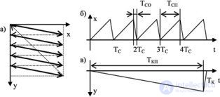
Fig. 9.1 Progressive scan image:
a) the formation of the raster; b) the horizontal coordinate of the decomposition element (line scan); c) the vertical coordinate of the decomposition element (scan across the frame)
The sequential selection of elements in a row and the sequential search of lines in a frame are provided by a special sweep device. The successive changes in the coordinates of the selected element horizontally and vertically correspond to sawtooth voltage sweep in rows and frames, shown in the figures, respectively, 9.1, b and 9.1, c.
The following notation is used in the figure: x and y, respectively, the horizontal and vertical coordinates of the decomposition element; T With - the period of decomposition of the image horizontally, and, T SP - the duration of the forward stroke of the sweep on the line, T WITH - the duration of the reverse; T To - the period of the scan image along the vertical, and, T KP - the duration of the forward stroke along the vertical. In the case of progressive scan of the image, the scanning period over the frame is a multiple of the scanning period along the line T K = N * T C , where N is an integer. In this case, after iterating through all the decomposition elements of the previous frame, the sweep device will transmit information about the first element of the first row of the next frame.
The number of elements of the expansion horizontally and vertically is selected based on the characteristics of the person’s vision. The best perception of the object is provided if it is viewed in a vertical plane at an angle of view equal to 15 °, and in a horizontal plane at an angle equal to 20 °. Such ratios are provided at distances to a rectangular screen, 5 times the height of this screen.
The number of lines is selected from the condition of the required resolution in the vertical direction (vertical clarity). It should not be noticeable line structure of the image. Different standards use a different number of lines. In domestic television broadcasting 625 lines were taken in the frame.
A full frame image is generated by sequential scanning of all lines. If the frame rate is higher than the critical flicker frequency, the image of the frame looks like a single picture, and no flicker is felt when changing frames.
In broadcast television, interlaced scanning is more effective. With this method of scanning the image, the entire cycle of the formation of the scan on the interval of one frame is divided into two subcycles. In the first subcycle, all odd lines are processed, in the second subcycle, all even lines are processed. The full frame image is transmitted in two sweep cycles. In order to ensure the formation of interlaced scanning, there must be an odd number of lines in the frame. For the formation of two fields with shifted rows, the formation of the second half-frame must begin in the middle of the line.
The interlaced raster structure is shown in Figure 9.2, a. In the domestic broadcast television, the frequency of changing half-frames was chosen to be greater than the critical flicker frequency and equal to the frequency of the AC supply network of 50 Hz. This choice of frame rate reduces the negative effect of the background of alternating current on the work of the television system nodes and, ultimately, on the formation of the image. Figures 9.2, b and 9.2, c show the signals, respectively, of the horizontal and vertical scans.
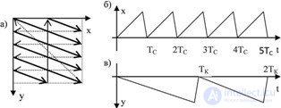
Fig. 9.2 Interlaced Image:
a) the formation of the raster; b) horizontal scanning signal; c) frame scanning signal

Comments
To leave a comment
Devices for the reception and processing of radio signals, Transmission, reception and processing of signals
Terms: Devices for the reception and processing of radio signals, Transmission, reception and processing of signals