Lecture
Selectivity is the ability of a radio receiver to select a useful signal and weaken *** the effect of interfering signals (interference) using various methods of selectivity: frequency, time, spatial, polarization, etc.
Temporal selectivity is mainly used when receiving pulse signals, when the moment of their appearance is known quite accurately. In this case, the gating method is used, when the receiver is opened only for the time of the expected arrival of a pulse signal. The rest of the time the receiver is closed, which reduces the impact of interference.
Spatial selectivity is carried out with the help of highly directional receiving antennas, and at present, by controlling phased antenna arrays (PAR). If the signal sources and interference are spaced apart in angular directions, it is possible to significantly weaken the level of external interference at the receiver input, forming a maximum antenna pattern in the direction of the signal source, and zeroes in the radiation pattern in the source direction.
Polarization selectivity is of primary importance. This is explained by the fact that in broadcasting and in the main radio communication systems, signals differ in frequency and their separation can be most easily accomplished using resonant circuits and filters.
Unlike sensitivity, selectivity (selectivity) cannot be assessed by a single number, since Due to the presence of electronic devices with non-linear characteristics, the effects caused by the simultaneous transmission of signals and interference may differ from those that would occur if they were received separately. Therefore, to assess the selectivity using various ways to assess the selectivity. These include evaluation of single-signal selectivity and evaluation of effective (multi-signal) selectivity.
a) Single-signal selectivity.
With the simplest single-signal estimation method, the selectivity is described by the frequency response of the receiver when a single low-level harmonic signal is applied to its input without causing non-linear effects. The gain of the radio frequency path K depends on the frequency f and at  . reaches maximum value
  . Magnitude
  characterizes the attenuation of interference. Addiction
  is a characteristic of selectivity.
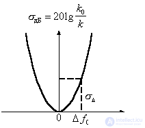
Figure 3.4.
On the graph on the x -axis lay the frequency f or detuning  , and the vertical axis
  in relative units or in decibels

Selectivity is quantified by attenuation.  at some kind of frustration
  both ways relatively
  .
.
So, when testing broadcast receivers of the low-to-high bands, often = 9 kHz, which corresponds to the width of the allocated frequency channel. Then the frequencies  9 kHz will be the carrier frequencies of adjacent channels, and the corresponding values will characterize the adjacent channel selectivity
  kHz
kHz
For a superheterodyne detector, the image channel selectivity is estimated by attenuating  at
at  .
.
Sometimes selectivity is assessed by the degree of closeness of a real characteristic.  to perfect. Ideal in terms of selectivity is a rectangular characteristic , for which
  = 0 within bandwidth and
  beyond.
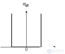
Figure 3.5.
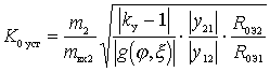
The degree of closeness of the real characteristics to the ideal characterize the coefficient of squareness characteristics 
,Where  - bandwidth of 3 dB (
  = 0.7);
 - bandwidth level
  db
db
b) Effective (multi-signal) selectivity takes into account non-linear effects with simultaneous signal and intense interference.
There are several types of multi-signal selectivity; the main ones are two- and three-signal selectivity.
Nonlinear effects in amplifying and converter stages, mainly due to the nonlinear current-voltage characteristic of active devices with high signal levels or interference, can cause the following phenomena.
Compression of the amplitude of the radio signal, i.e. violation of the linear relationship between the amplitudes of the signal at the output and input of the cascade. This phenomenon occurs in the mode of a large useful signal and is quantitatively characterized by a compression ratio.
 ,
,
Where  - change in the average slope for the period of the input signal;
 - the slope at the working point of the IVC of the electronic device.
The compression of the amplitude of the signal in series-connected n stages is equal to the algebraic sum of the compression factors of each stage.
The blocking of the useful signal, expressed in the change of the transmission coefficient of the receiving path under the action of interfering signals, whose frequencies differ from the frequencies of the main and side channels of reception. Most often, the transmission coefficient decreases, which leads to a decrease in the signal-to-noise ratio at the output of the receiver or a decrease in its sensitivity. Quantitatively, this phenomenon is estimated by the blocking coefficient.
 ,
,
Where  - the amplitude of the signal component due to interference;
 - amplitude of the signal component in the absence of interference.
For multi-stage device  equal to the sum of these coefficients of individual cascades.
Cross distortion of radio signals, manifested in the transfer of modulation from an interfering out-of-band signal to a useful one. This phenomenon may occur when the wanted signal passes through a parametric cascade, a complex transfer function.  which varies in time according to the law of a strong interfering out-of-band signal located in frequency on the slopes of the frequency response of a given cascade. When the modulus of the transfer function changes
  in time with the change of the interfering signal amplitude cross modulation occurs, and when the argument changes
  - angular cross modulation.
Quantitatively distortions are estimated by the cross-distortion factor.
 ,
,
Where  - amplitudes of the spectral components formed after detection due to cross modulation;
- amplitude of the useful component after detection.
Intermodulation (intermodulation) between interfering out-of-band signals, as well as between out-of-band signals and noises.
As we noted earlier (when considering a superheterodyne receiver), intermodulation is the process of generating interference with combinational frequencies close to the signal frequency, due to the effect of two or more intense interference at different frequencies on a nonlinear element.
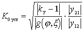
Intermodulation is quantitatively estimated by the level of the components of mutual modulation at the output of the device with respect to the amplitude of one of the same interacting signals, which is defined as the two-signal nonlinear distortion coefficient.
The adjacent channel selectivity is the ability of the receiver to receive a useful signal at a given channel frequency with a given error probability in the presence of an interfering signal on the adjacent channel. Usually, to set the selectivity for the adjacent channel, the requirements are imposed on the depth of suppression of the frequency of the first and second adjacent channels. A graph illustrating receiver requirements for adjacent channel suppression is shown in Figure 1.
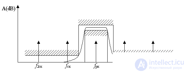
Figure 1. Adjacent channel receiver selectivity (single-signal selectivity)
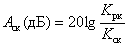
Suppression of the adjacent channel in this case is defined as the ratio of the transmission coefficient of the main path of the receiver on the working channel to its transmission coefficient on the adjacent channel:
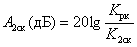
Sometimes, in addition to the requirements for suppressing the adjacent channel, the receiver is required to suppress the second adjacent channel f2ск and more distant channels:
Typically, the requirements of the adjacent channel selectivity are satisfied by the filter of the main selectivity of the main reception path. Often, the requirements for suppressing the first adjacent channel and suppressing remote channels are different. In this case, the receiver selectivity is given by a mask, an example of which is shown in Figure 2.
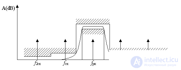
Figure 2. The mask of the selectivity of the receiver on the adjacent channel
The suppression of the signal of the adjacent channel, depending on the destination of the receiver and the type of the received signal, can vary and currently can reach 80 dB in communication receivers.
In a number of receiver circuits, such as superheterodyne or superheterodyne with double frequency conversion, in addition to the main reception channel, there are side reception channels, such as a mirror channel of the first and second intermediate frequency, direct passage through the channel of the first and second intermediate frequencies. These channels result from the imperfection of the main reception path. The reasons for the formation of these reception channels will be discussed in more detail in the following chapters.
When specifying the requirements for the radio receiver, parameters are set that determine the suppression of signals of side reception channels. Typically, the requirements for side channels of reception are set not worse than the suppression of the adjacent channel, and in some cases much more stringent. Suppression of side channels in modern analog reception paths is at least 80 dB.
Intermodulation - the phenomenon of the appearance at the output of a receiver when two or more interferences occur at its input, the frequencies of which do not coincide with the frequencies of the main and side reception channels.
As a result of the interaction of interference with frequencies f 1 and f 2 on the nonlinear elements of the receiving device, intermodulation products appear:
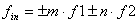 . (one)
In this case, in the receiving path, an intermodulation interference signal can be obtained with a frequency equal to the frequency of the useful signal or falling into the sideband bands of the receiver. Such interference is processed in the receiving device together with the useful signal, degrading the quality of the received message. The mechanism of the appearance of the spectral components is described in detail in the article diode mixer and in the literature [3], and the products of nonlinear conversion up to the third order are shown in the same article in Figure 3.
Рассмотрим механизм возникновения интермодуляционных искажений. Пусть на вход радиоприемного устройства воздейтвуют две помехи с частотами f 1 и f 2
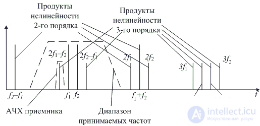
Рисунок 1. Механизм возникновения интермодуляции
При измерении интермодуляционных помех на вход приемника подается два гармонических сигнала, настроенных на частоты второго и четвертого соседних каналов. Как это хорошо видно на спектре сигнала на выходе первого усилительного каскада, приведенном на рисунке 2, выше или ниже принимаемой частоты будут подаваться эти частоты, для возникновения интермодуляционной помехи на принимаемой частоте значения не имеет. Методика измерения интермодуляционных помех приведена в [4].
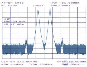
Рисунок 2. Спектр сигнала при подаче на вход приемника двух гармонических сигналов одинаковой амплитуды
Коэффициент интермодуляционных искажений второго порядка определяется как отношение амплитуды комбинационной составляющей f 2 ± f 1, к амплитуде одного из входных сигналов. Обычно этот коэффициент выражается в относительных едининицах (дБс) — децибеллах относительно несущей. Еслидиапазон принимаемых частот радиоприемного устройства достаточно узок, как это имеет место для систем УКВ мобильной связи или систем сотовой связи, то комбинационные частоты второго порядка образуются за диапазоном принимаемых частот и подавляются входным фильтром приемника.
На практике для количественной оценки интермодуляционных искажений (InterModulation Distortion, IMD) используют коэффициенты, вычисляемые при подаче на вход приемника двух внеполосных гармонических сигналов f 1 и f 2 с равными амплитудами:
коэффициент интермодуляционных искажений третьего порядка — отношение амплитуды комбинационной составляющей 2∙ f 2 – f 1 (или 2∙ f 1 – f 2) к амплитуде одного из этих сигналов на входе.
Продукты третьего и более высоких порядков, возникающие при смешивании двух интерферирующих радиосигналов могут создавать сигнал помехи в рабочем канале. Так как полоса обрабатываемых частот обычно ограничивается в преселекторе на входе приемника, то нелинейность измеряется путем подачи на вход приемного устройства двух сигналов равной амплитуды с частотами f 1 и f 2, достаточно близко расположенными к частоте настройки приемника. При этом измеряется уровень продуктов интермодуляции третьего порядка 2∙ f 1 – f 2 и 2∙ f 2 – f 1. Другие комбинационные продукты обычно находятся вне полосы рабочих частот приемника и подавляются фильтром основной избирательности.
Подавление эффекта интермодуляции (Intermodulation response rejection) — мера способности приемника приниматьтребуемый сигнал на частоте рабочего канала в присутствии двух или более сигналов помех, которые имеют определенное соотношение частот с требуемым сигналом.
Нелинейные искажения принимаемого сигнала в приемном устройстве могут возникать не только в том случае, если его уровень значителен, но и при воздействии сильной внеполосной помехи. Нелинейность приемного тракта приводит к тому, что при появлении помех, воздействующих на вход приемника на частотах, которые не совпадают с частотами основного и побочных каналов приема, происходит изменение уровня полезного сигнала или изменение отношения сигнал/шум на выходе приемника. Воздействие мощной помехи на вход приемника приводит к снижению коэффициента усиления устройства. Такое явление называется блокированием приемника (Blocking). Численно блокирование может быть оценено с помощью коэффициента блокирования:
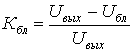
где: U вых — амплитуда сигнала на выходе приемника при отсутствии помехи на входе;
U бл — амплитуда сигнала на выходе приемника при действии помехи на входе.
Таким образом, при отсутствии блокирования в приемнике К бл = 0. Коэффициент блокирования тем сильнее, чем больше уровень помехи на входе и чем ближе частота помехи к частоте полезного сигнала. Это влияние определяетсяизбирательностью приемника по соседнему каналу.
Еще одним параметром оценки линейности тракта радиоприемного устройства является однодецибельная точка компрессии, (1-dB compression point), определяемая как точка на амплитудной характеристике, в которой коэффициент усиления по мощности уменьшается на 1 дБ по сравнению с идеальным. Иллюстрация определения однодецибельной точки компрессии радиоприемного устройства приведена на рисунке 1.
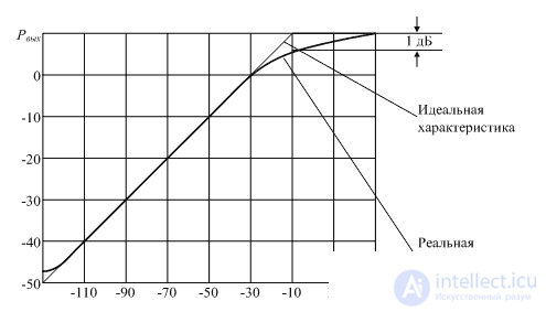
Рисунок 1. Иллюстрация определения однодецибельной точки компрессии

Comments
To leave a comment
Devices for the reception and processing of radio signals, Transmission, reception and processing of signals
Terms: Devices for the reception and processing of radio signals, Transmission, reception and processing of signals