Lecture
And not everyone knows that synchrodin is not quite the exact name of the type of such a receiver.
And very few people know that it was also called “homodyne” receiver, or so — superheterodyne with zero IF, or simply — heterodyne receiver.
If you call it as it is now, then almost everyone will understand what it is about - "receiver with direct frequency conversion."
After “voicing” of this name, there is no point in telling the principle of its work.
Everything is very simple: there is an input circuit, a local oscillator operating at the receive frequency (or a multiple of it), the input signal is mixed with the local oscillator frequency, the resulting beat signal (if it is an SSB signal, then a voice signal) in the audio frequency range is amplified by a low-frequency amplifier . This is the principle of direct conversion (without the use of a special detector).
The principle of operation is quite different from the principle of operation of other types of receivers (direct amplification, superregenerative, superheterodyne, and others, therefore, this type of circuit was assigned its own (distinctive) niche in the classification.
In support of simplicity, say, the concept of receivers of this type, which are listed below
Note: there is also a regenerative receiver circuit here - this is not an error, when adjusting the R6, it can also turn into a synchrodin (according to the author).
A direct conversion radio receiver , also called homodyne or heterodyne, is a radio receiver in which a radio signal is directly converted into an audio signal using a low-power oscillator (heterodyne) whose frequency is (almost equal) or a multiple of the received signal frequency. By the similarity of the operating principle, such a receiver is sometimes called a superheterodyne with zero intermediate frequency.
The first direct conversion receivers appeared at the dawn of the radio, when there were no radio tubes yet, communications were made on long and superlong waves, transmitters were spark and arc, and receivers, even coherent ones, were detector ones.
It was noted that the sensitivity of the detector receiver to weak signals increases significantly if the receiver had its own low-power oscillator operating at a frequency close to the frequency of the received signal. When receiving a telegraph signal, beats were heard with an audible frequency equal to the difference between the local oscillator frequency and the signal frequency. The first heterodyne served as the machine generators, then they were replaced by generators on vacuum tubes.
By the 1940s, direct conversion receivers were supplanted by direct amplification receivers with a regenerative detector and superheterodyne. This was due to the fact that the main amplification and selection of the receiver of direct conversion was carried out at a low frequency. Build on the amplifier LF amplifier with high sensitivity and low noise figure is difficult. The revival of direct conversion receivers began in the 60s with the use of a new element base - operational amplifiers, transistors. It has become possible to use high-quality active filters on operational amplifiers. It turned out that with comparative simplicity, direct conversion receivers show characteristics comparable to superheterodyne. In addition, since the local oscillator frequency of the direct conversion receivers can be two times lower than the signal frequency (with certain types of mixer), it is convenient to use them for receiving UHF and microwave signals. Of particular interest, direct conversion receivers have evoked among short-wave radio amateurs, since this principle allows even a beginner to build a receiver suitable for broadcasting with minimal time and money. In the USSR, the main merit in the repeated popularization of the direct conversion technique belongs to V. T. Polyakov. Since its first publications on this topic (the first half of the 1970s), a direct conversion receiver on three to five transistors has become the typical first design of a novice shortwave.
The key drawback, which is the key advantage of this type of receivers, is the proximity of the receiving mirror channel to the received channel. In practice, these are adjacent channels, and it is quite difficult to filter the reception channel at a low frequency. In some applications, the mirror channel does not need to be filtered at all, since it is almost guaranteed free. This situation is observed in VHF broadcasting, when, when licensing frequencies, the adjacent channel next to a powerful radio station is tried to be left empty. Therefore, direct conversion receivers for VHF can not be equipped with an input filter at all, and everything else easily fits into one chip without attached elements. These very cheap and miniature receivers are now embedded in electronic gadgets such as cell phones.
In the case of using a direct conversion receiver on HF, for example, for amateur radio communication, dual-band reception becomes a serious drawback, since there is a lot of interference from neighboring stations on narrow amateur bands. You can suppress the unwanted reception channel using the phase compensation method. However, the receiver immediately loses its most important advantage - the simplicity of the device and adjustment.
The considered scheme of the detector receiver allows to obtain information about the amplitude of the received radio signal. The efficiency of the detector determines the sensitivity of the receiving device.
The first direct conversion receivers appeared at the dawn of the development of radio engineering, when there were no radio tubes yet, communications were conducted on long and superlong waves, transmitters were spark and arc, and receivers, even professional ones, were detectors.
It was noticed that the sensitivity of the detector receiver increases significantly if the detector is applied to oscillations of a low-power generator operating at a frequency close to the frequency of the received signal. When receiving a telegraph signal, beats were heard with an audible frequency equal to the difference between the local oscillator frequency and the signal frequency. Consider the nature of this phenomenon.
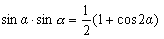
The selectivity of the detector receiver in frequency is provided by a band-pass filter included at the input of the amplitude detector. The same problem can be solved if we transfer the energy of the received signal to the low-frequency region. In this case, the frequency selectivity can be implemented by a low-frequency filter, the complexity of which with the same characteristics of the suppression of the adjacent channel will be two times less. The transfer of the radio frequency spectrum to the low frequency range can be accomplished using the following trigonometric transformation:
As a second sinusoidal signal with a frequency that coincides with the frequency of the received radio signal, a signal from a local generator, called a local oscillator, is used. The voltage at the output of the multiplier, which in this case is called a synchronous detector, will be recorded as follows:
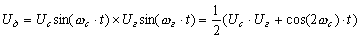
The voltage of twice the frequency of the radio signal can easily be suppressed by a low-frequency filter. The process of transferring the modulating frequency from the frequency of the working channel to the zero frequency is illustrated in Figure 1.
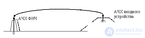
Figure 1. Process working channel at zero frequency
The block diagram of the direct conversion receiver that implements the principle of transfer of the useful signal spectrum described above to the low-frequency region is shown in Fig. 2.
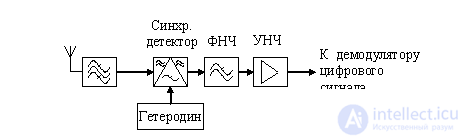
Figure 2. Block diagram of the direct conversion receiver
In this receiver, a band of frequencies in which the input signal is present is allocated with a band-pass filter, then the spectrum is transferred to the low frequency range by a synchronous detector. Suppression of the frequencies of adjacent channels in this scheme can implement both a bandpass filter at the detector input and a low-pass filter located at its output. It is known that the complexity of a low-pass filter is two times lower than the complexity of a band-pass filter with the same selectivity. Therefore, the direct conversion receiver circuit is more advantageous both in terms of reliability and in terms of the cost of the device.
Let us determine the requirements for a low-pass filter (LPF) of a direct conversion receiver. Figure 3 shows the spectra of the useful signal and the signal of the adjacent channel. The same figure shows the amplitude-frequency characteristic of the low-pass filter of the synchronous detector, which is part of the direct conversion receiver.
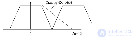
Figure 3. Requirements for the low-pass filter in the direct conversion receiver
The complexity of the low pass filter depends on its order. Requirements for the order of the filter receiver direct conversion are set by the slope of the slope of its amplitude-frequency characteristic of the filter (AFC). In general, these requirements depend on the specific type of signal used in this communication system.
Let the frequency of the adjacent channel be three times the upper frequency of the useful signal. Then the frequency detuning Ffk = fsk / fv will be equal to 3, and the first order filter will suppress this frequency three times. The same figure can be expressed in decibels:

Usually requires the suppression of the adjacent channel at least 60 dB. Then the necessary order of the low-pass filter can be determined using the following formula:
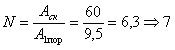
So, in this case, a sixth-order filter is not enough and a seventh-order Butterworth filter is required.
In modern versions of the receiver direct conversion at the output of the filter is an analog-to-digital converter and a digital signal processing circuit. In this case, the task of suppressing the adjacent channel can be carried out by this digital circuit, and then the requirements for the filter located at the output of the multiplier can be reduced to the requirements for the first order filter, and its task will be to suppress the high-frequency images of the digital filter bandwidth (anti-aliasing filter) .
The requirements for a low-frequency amplifier are determined by the required gain of the useful signal. Often the value of the required gain reaches several thousand. Then the noise characteristics of the amplifier come out on top. In this case, it is desirable to limit the signal bandwidth at the output of the ULF to suppress its out-of-band noise.
Changing the level of the useful signal depending on the propagation conditions of radio waves may require the use of an automatic gain control circuit (AGC). This scheme will be considered by us in subsequent chapters.
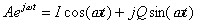
In the scheme considered in Figure 2.9, it is required to ensure accurate synchronization of the local oscillator signal and the received signal. This is quite difficult to do. In addition, it should be borne in mind that the original signal may contain information embedded in the phase of the high-frequency signal, therefore, in order not to lose it, it is necessary to form a complex exponent signal as a heterodyne signal, or, in other words, a sinusoidal and cosine signal :
Since the phase increment in a signal can be both positive and negative, both positive and negative frequencies can be present in it (Figure 2.10). This situation is illustrated in Figure 2.13.
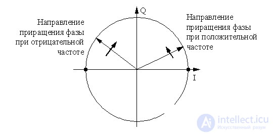
Figure 4. The direction of rotation of the phase vector at positive and negative frequencies
To transfer the spectrum of the original signal in this case, we need two signal multipliers. As a result, two quadrature signals I and Q will be generated at the output of the circuit. The radio receiver constructed according to this principle is called a direct conversion receiver. Its structural diagram is shown in Figure 3.
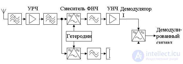
Figure 5. Block diagram of the direct conversion receiver
In this scheme, the suppression of frequencies of the adjacent channel is carried out by low-frequency filters, which are located immediately after the frequency converters (multipliers). After suppression of interference, the main amplification of the received signal is performed. The final demodulation of the received signal is performed by a digital signal processing circuit, which can be performed either on a signal processor (SP) or on a programmable logic circuit (FPGA).
To build a low-pass filter with the same slope of the slope, the frequency response requires two times fewer elements compared to a band-pass filter, therefore, from a mathematical point of view, this scheme is ideal when building radio receivers.
Direct conversion circuitry makes it easy to build multi-band receivers. To switch from one band to another, it is enough to change the frequency of the local oscillator. It is very convenient for the implementation of GSM, GPRS and 3G receivers simultaneously.
Unfortunately, at present it is very difficult to implement multipliers with a sufficiently large dynamic range, and only with the development of digital technologies, this scheme gradually becomes more and more widespread and with its help it is possible to realize more and more high-quality receivers.
If an ideal multiplier could be implemented in the direct conversion receiver circuit, then no more block at the input of the synchronous detector would be required. Unfortunately, this is not the case. Therefore, at the input of the multiplier, you have to put a band-pass filter, from which you want to reduce the number of interfering signals to the input of the synchronous detector. This allows you to bring its properties to the properties of an ideal multiplier. However, the requirements for a bandpass filter are much lower than the requirements, if the bandpass filter were to perform the suppression of the adjacent channel.
.
| The main parts of the radio |
|
|---|
| Radio receivers |
|
|---|

Comments
To leave a comment
Devices for the reception and processing of radio signals, Transmission, reception and processing of signals
Terms: Devices for the reception and processing of radio signals, Transmission, reception and processing of signals