Lecture
In radars with a transmitter on an auto-oscillator in the output stage, a number of destabilizing factors lead to fast and slow changes in the carrier frequency. For example, the absolute frequency care in the 10 cm band can be several MHz. In this case, with a constant frequency of the local oscillator, the signal spectrum goes beyond the bandwidth of the IFA receiver and the signal will be significantly suppressed or lost.
The currently existing AFC devices can compensate for instabilities whose frequencies do not exceed several megahertz.
Purpose The AFC system maintains the nominal value of the intermediate frequency of the receiver with a given accuracy by automatically changing the frequency of the transmitter generator and (or) the local oscillator. In other words, the AFC system is designed to stabilize the frequency of oscillations of simple signals and the given laws of variation of the frequency of complex signals.
A simplified diagram of a single-channel AFC is shown in Figure 3.55. In the mixer (CM), the oscillations of the difference frequency of adjustable and reference oscillators are distinguished. After amplification in the UPCH, this oscillation is fed in the PLL system to the frequency discriminator (BH), and in the PLL system to the phase discriminator (PD). If in the region of stable operation of the system the frequency (phase) of the oscillating waveform is different from the transition frequency of the BH (phase of the reference signal), then the error signal voltage appears at the discriminator output. After filtering in the low-pass filter (LPF) and amplification in the error signal amplifier (USO), this voltage is applied to the frequency-controlling element, which changes the oscillator frequency in the direction of reducing the deviation caused by the interference. The specific scheme of the AFC system is determined by the requirements placed on it and depends on the type of radar and the location of the auto-tuning device in it.
Existing HR systems can be classified by the following features:
by the principle of action;
by type of discriminator;
by parameter, the constancy of which is provided by the system;
the type of ruler used;
according to the method of setting the stabilized generator to the desired frequency;
by type of frequency reference;
on the speed of impact on the actuator.
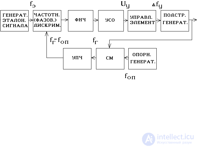
Fig.3.55. Simplified single channel AFC circuit.
According to the principle of the AFC system, there are:
continuous (analog);
impulse;
digital;
analog to digital.
By the form of the discriminator, the AFC systems are divided into two classes:
frequency auto-tuning systems (CHAP);
phase-locked loop systems (FAP).
In the CHAP system, a frequency discriminator (BH) is used, which reacts to the magnitude and sign of the deviation of the stabilizing frequency f g from the reference f e and produces a voltage of the error signal U d determined by the magnitude and sign of this deviation f = f e - f g, i.e. . U d = f ( f ).
In the PLL system, a phase discriminator (PD) is used, which reacts to the magnitude and sign of the phase deviation of stabilized oscillations g from the phase of reference oscillations e and generates a voltage of the error signal Ud depending on the phase difference = e - g, t. e. U d = f ().
According to the parameter, the constancy of which is provided by the system is distinguished:
difference frequency auto-tuning system;
absolute frequency auto-tuning system.
The difference frequency auto-tuning system ensures the constancy of the frequency difference between the radar transmitter and the receiver's local oscillator and the equality of this difference to the nominal value of the intermediate frequency f a p with a permissible error.
According to the method of obtaining the control voltage, such a system refers to combined or single-channel. It maintains a constant difference in the frequencies of the incoming signal and the local oscillator, for example, f с - f g. The frequency standard in it is the transition frequency of the BH, i.e. this frequency is within the passband of the discriminator at which its output voltage is zero.
There are also two-channel AFC systems. The principles of their work will be discussed below.
According to the type of ruler used by the AFC system, they can be:
electronic, i.e. those in which the control frequency of the generator being stabilized is carried out in a purely electronic way, by changing the voltage or current (for example, by changing the voltage on the reflector of the klystron generator);
Electromechanical, in which the frequency control is carried out using electric motors or solenoids, mechanically changing the parameters of the oscillating circuits;
combined, combining both electronic and electromechanical tuning.
Electronic systems are mainly used in the AFC systems of the radar operating without protection from intense interference, or in the radar with the MTS in amplitude mode.
Combined systems involve the use of electronic control in the amplitude mode and electromechanical control in the coherent mode.
According to the method of setting the stabilized generator of the AFC scheme, there are distinguished: searchless, or tracking; search.
In the tracking system, manual pre-tuning and manual signal frequency search are required after it has been lost by the system. In a search engine, these operations are automated.
By type of frequency reference system of the AFC can be:
with active standards, which are highly stable low-power generators (quartz or molecular);
with passive standards, the role of which is performed by high-Q resonant systems or gas devices with a narrow absorption spectrum at a certain frequency.
According to the speed of impact on the actuator of the AFC system, they can be: inertial; high-speed; "Instant"; intermittent.
Fig.3.56 reflects the possibility of different systems of frequency control by time regulation. The solid line shows the energy spectrum of the fluctuations in the frequency of the unstabilized oscillator. The dotted lines show the possibility of reducing its levels by different systems of frequency control systems.
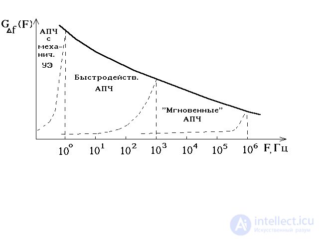
Fig.3.56. Capabilities of various systems for time management regulation.
For control systems with mechanically controlled elements, a long regulation time t of AFCs> 0.5 ... 1 s is typical. (low speed), so they reduce only low-frequency fluctuations of frequencies F <1 ... 2 Hz. High-speed AFC systems suppress the components of the fluctuation spectrum of the oscillation frequency of the oscillator to frequencies F ≤ 1 ... 5 kHz. As is well known, the presence of fluctuation components at these frequencies in the spectra of a transmitter or a local oscillator signal leads to a deterioration in the performance of the MHD systems of coherent pulsed radar (reduction in the sub jamming visibility coefficient). “Instant” AFCs are used to reduce the frequency deviation within a pulse during the formation of complex, for example, chirp signals. The regulation time of such systems is 0.5 ... 1 μs.
The efficiency of the AFC system is estimated by the frequency response, which expresses the dependence of the voltage on the system output on the detuning value on the nominal frequency.
The main characteristics of the AFC system include: setting band (capture band); frequency tuning accuracy f AFC; speed V AFC or auto-tuning time t AFL.
The setting range is the frequency range within which the searchless auto-tuning of the generator frequency with a given accuracy is provided. The value of the setting bandwidth is determined by the discriminator bandwidth (Fig.3.57).
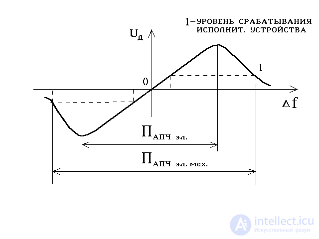
Fig.3.57. Characteristics of the discriminator system AFC.
If the radar has an operating frequency tuning system, the setting band must satisfy the condition
P AFC | f SP g | + | f JV mg |, (3.34)
where f SPG, f SPmg are the maximum frequency setting errors, respectively, by the transmitter generator and the local oscillator when the operating frequency of the radar station is tuned.
In the absence of an adjustment system
P AFC | f max G | + | f max MG |, (3.35)
where f max G, f max MG are the maximum possible frequency drifts of the transmitter generator and local oscillator, respectively, due to destabilizing factors.
If it is necessary to ensure high values of PLL, preference should be given to electromechanical systems of PFC, since in PFC electronic systems, an increase in P of PFC is associated with an impracticable contradiction between the range of electronic tuning and the stability of the transmitter generators and the local oscillator.
The accuracy of the frequency control is characterized by the static error of the AFC system, which is determined by the ratio
f = f beg / (1 + K oc · S d · S y), (3.36)
where f beg is the initial detuning of the frequency of the generator being stabilized relative to the frequency of the standard; K OS - the resulting gain of the open-loop feedback system; S d, S y - the slope of the characteristics of the discriminator and the ruler, respectively.
From the relation (3.36) it follows that in order to increase the accuracy of the auto-tuning of frequencies, it is necessary among other things to increase the steepness of the discriminator characteristic. However, this reduces the bandwidth of the discriminator, and hence the setting bandwidth of the AFC. To resolve this contradiction, the AFC system with two feedback loops is used, which are connected to one ruler (Fig.3.58), i.e. dual channel AFC systems.
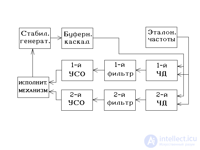
Fig.3.58. AFC system with two feedback loops
The first feedback loop has a discriminator with a wide bandwidth and a setting band that exceeds the range of possible initial detunings of the generator. Due to the low slope of the discriminator characteristic, the residual detuning during operation of this OS loop will be great, but always less than half the setting band of the second OS loop, which has a discriminator with a narrow bandwidth, a greater steepness and, therefore, providing a much smaller maximum residual detuning.
The speed of automatic frequency control is one of the most important characteristics of AFC systems. Requirements for it are determined by the operating mode of the radar.
In the amplitude mode, there are no limitations on the speed of the AFC. Modern electronic systems of the AFC when operating the radar in amplitude mode (without MTS) provide an auto-tuning speed at which
t AFC = (0.5 .... 0.7) · i,
where t AFC is the time during which the initial detuning is reduced to residual; i - the duration of the probe pulse.
When the radar operates in coherent mode, changing the frequency of the transmitter generators or the local oscillator during auto-tuning leads to the expansion of the fluctuation spectrum of the signals at the input of the MTS system and, consequently, to a decrease in the value of the passive interference signal suppression factor.
Therefore, in the coherent mode of operation of the radar, the permissible speed of the AFC is limited to the value at which the realized suppression factor of the passive interference signals decreases by the allowable number of times. This condition is represented as
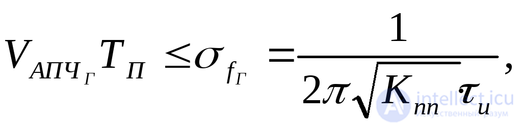 (3.37)
if the transmitter generator frequency changes during auto-tuning, and
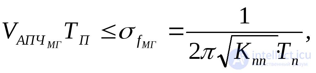 (3.38)
if the local heterodyne adjusts.
From relations (3.37) and (3.38) it follows that the speed of the AFC when adjusting the transmitter generator is limited by the condition
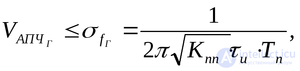 (3.39)
and when adjusting the local heterodyne
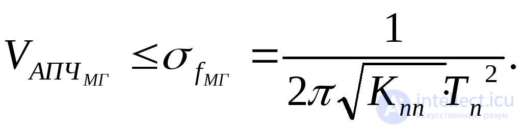 (3.40)
Comparing these relations, we can conclude that the permissible speed when adjusting the transmitter generator is Q- times higher than when adjusting the local heterodyne. This means that when operating the radar in coherent mode, preference should be given to the AFC generator transmitter.
In cases where the auto-tuning time is unacceptably long due to restrictions on the permissible speed of the AFC, the intermittent operation of the AFC system is applied.
The timing diagram (Fig.3.59) explains the essence of the work of a discontinuous AFC system.
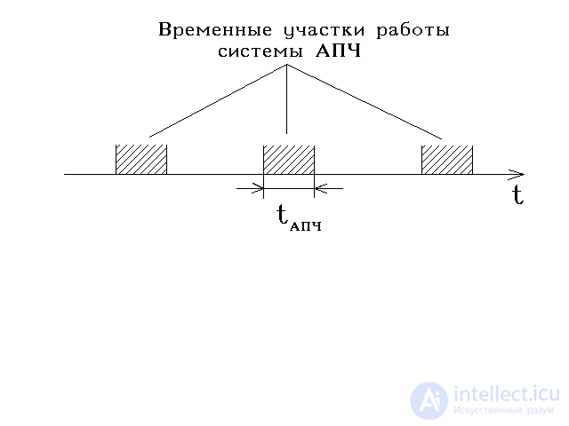
Fig.3.59. Temporary areas of the HR system.
During operation of the HRC system, the SDC system does not work. The time interval between successive instants of switching on the AFC system is either set constant, taking into account the speed of the transmitter generator frequency and the local heterodyne due to destabilizing factors, or changes automatically. In the latter case, the moment of switching on the AFC system is determined by the moment when the detuning frequency out of the permissible limit begins.
Thus, the main requirements for the AFC system are as follows: ensuring a given frequency stability (phase) of simple and complex signals; implementation of the required speed; resilience; ability to work with both small and large initial detuning; high reliability; simplicity of designs; acceptable cost of operation.
The frequency control object in the AFC system can be an auto-oscillator or a local oscillator. The local oscillator (MG) is the most advantageous object of frequency change in speed in the amplitude mode, the setting band and the power consumption level of the actuator.
However, in two-channel AFC systems with switching of the restructuring object, accurate AFC can be performed by changing the frequency of the oscillator. For example, the problem is solved in the radar 5N84A.
As an example, we will consider a single-channel AFC system with adjustment of the local heterodyne frequency (Fig. 3.60).
In the AFC systems, the generator and the local oscillator frequency are used as the initial parameters, the difference of which should be equal to the nominal value of the intermediate frequency. It is practically easier to measure the drift of high-frequency signals at an intermediate frequency, while it is much easier to achieve high system sensitivity to detuning.
Conversion and separation of the difference (intermediate) frequency is performed by the AFC mixer, similar to the signal mixer in the receive path. The only difference is that the reflected signal and the local oscillator signal are fed to the signal mixer and the local oscillator signal and the transmitter at the time of its operation to the AFC mixer. The transmitter signal is fed through an attenuator in order to reduce its power to a value comparable to the power of the local oscillator.
The difference signal at the output of the mixer is amplified by auxiliary UPCH. UPCH bandwidth should be slightly larger than the capture bandwidth. Direct measurement of the frequency drift and the generation of the corresponding controlled error voltage is performed by the frequency discriminator, which converts the radio pulses of the difference frequency into a control voltage. The magnitude of this control voltage depends on the magnitude of the detuning, and the polarity of the detuning sign.
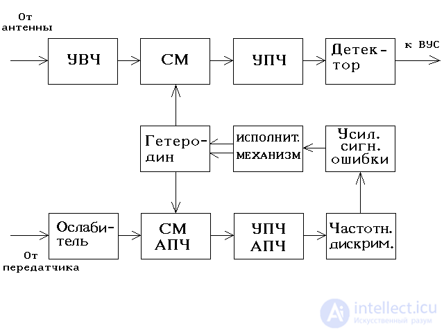
Fig.3.60. Single channel AFC system.
Basically, two types of frequency discriminators are used:
with interconnected tuned contours;
with interdependent parallel circuits.
The signal at the output of the frequency discriminator is a short-term video pulse of small amplitude, while the executive device requires a constantly operating error signal of the required level. Therefore, the pulse voltage from the output of the discriminator is amplified in power and converted to the form necessary for the operation of the actuating element.
If the heterodyne is a klystron, then a constant control voltage is generated on its reflector.
If the actuating element is an AC motor, then an alternating voltage is produced, the amplitude of which is given by the frequency drift from the intermediate one, and the phase by the drift voltage along the discriminator curve (Fig.3.57). The actuator changes the frequency of the local oscillator in the direction of decreasing the error signal to the level determined by the accuracy of the AFC system.
If the radar system uses the SDC with internal coherence, then, as a rule, intermittent AFCs are used, which prevents, as noted above, the parasitic phase incursions that are possible during continuous operation of the AFCs. In this case, discontinuous AFC systems incorporate a software device that breaks the AFC circuit and turns it on for a short time. For example, in the radar PRV-13, the AFC is turned on for 0.5 seconds every 22 seconds.
За короткое время работы система АПЧ успевает подстроить местный гетеродин. Нормальная работа системы СДЦ практически не нарушается, поскольку большую часть времени боевой работы РЛС местный гетеродин не подстраивается.
Прерывистая система АПЧ применима при условии высокой стабильности местного гетеродина, когда частота его за время между двумя воздействиями АПЧ не выходит за пределы допустимых значений.
Таким образом, к достоинствам одноканальной системы АПЧ относится простота и возможность работы в тех случаях, когда передатчик и приемник разнесены и находятся на разных транспортных единицах (объектах). Недостатки системы заключаются в том, что, во-первых, теряется информация о доплеровском смещении частоты сигнала, во-вторых, система оказывается подверженной воздействию внешних помех и при высоком их уровне может ложно подстраивать частоту гетеродина – не по частоте сигнала, а по частоте помехи.
Двухканальная система АПЧ (автономная система АПЧ) с переключением объекта подстройки применяется, например, в РЛС П-18 и 5Н84А, имеющих внутрикогерентную аппаратуру СДЦ, систему перестройки со значительной остаточной ошибкой и сравнительно узкополосный приемник (рис.3.61).
Режим грубой АПЧ включается при больших расстройках. При этом схема переключения канала не срабатывает и напряжение грубого дискриминатора поступает на исполнительное устройство, подстраивающее гетеродин.
По мере подстройки увеличивается напряжение на выходе резонансного усилителя и когда это напряжение достигнет определенного уровня срабатывает схема переключения каналов, которая включит режим переходной АПЧ на время 0,5 с.
Дискриминационные характеристики систем АПЧ РЛС 5Н84А грубого и точного каналов показаны на рис.3.62.
В этом режиме используется сигнал точного дискриминатора, но подстраивается по-прежнему гетеродин. Через 0,5 секунд автоматически включается режим точной АПЧ, при котором используется сигнал точного дискриминатора, то подстраивается генератор СВЧ. Возможны и другие варианты двухканальных схем АПЧ, например, электронная АПЧ клистрона.
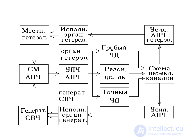
Рис.3.61. Двухканальная система АПЧ.
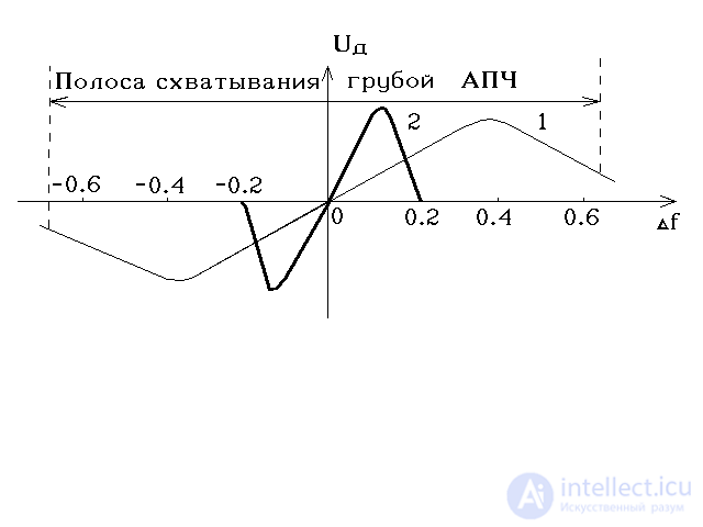
Рис.3.62. Дискриминационные характеристики систем АПЧ РЛС 5Н84А грубого и точного каналов
Таким образом, двухканальная система АПЧ разностной частоты свободна от большинства перечисленных недостатков одноканальной системы АПЧ. Она работает, используя часть мощности передатчика, отбираемой от последнего через аттенюатор, и не подвержена воздействию помех. Однако при этой схеме получение информации о доплеровском смещении частоты сигнала, отраженного от движущейся цели, невозможно, ибо хотя при изменениях частот передатчика и гетеродина разностная частота и будет поддерживаться постоянной со сколь угодно малой погрешностью, но изменение частоты передатчика неизбежно приведет к изменению доплеровского смещения частоты даже при постоянной скорости цели. Поэтому при необходимости точного определения скорости цели следует применять отдельные системы стабилизации частот передатчика и гетеродина.

Comments
To leave a comment
Devices for the reception and processing of radio signals, Transmission, reception and processing of signals
Terms: Devices for the reception and processing of radio signals, Transmission, reception and processing of signals