There are detector receivers without an audio amplifier and with an audio amplifier.
The detector receiver without UZCH. (May 7, 1895)
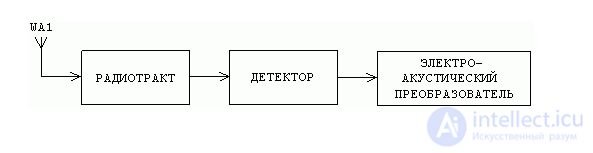
Figure 2.1.
The simplest detector receiver consists of a receiving antenna, which is an integral part of any receiving device, input device, detector and reproducing device, which usually are headphones.
Such a receiver is very simple in a schematic and constructive relationship and does not require power sources — the only source of energy here is signal energy accumulated in the telephone loop of the input device.
However, such a receiver has low sensitivity and selectivity (selectivity), a high level of non-linear distortion and cannot be used for receiving to a loudspeaker. Therefore, such receivers are currently almost not used.
The detector receiver with UZCH.
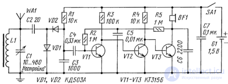
Figure 2.2.
Receiver parameters are significantly improved if an audio amplifier or video amplifier is turned on after the detector. Now it is possible to use a loudspeaker as a terminal device.
The main function of the radio receiver is to extract useful information from the received signal. In the simplest case, it is enough to demodulate the received signal. Such receivers are called detector receivers and are used in the cheapest wireless communication devices. The block diagram of the detector receiver is shown in Figure 1.
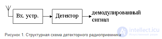
Figure 1. Structural diagram of the detector radio
Please note that even in such a simple circuit, an input device is required that matches the antenna impedance with the input impedance of the diode detector. As a detector, a circuit should be used that extracts information from the useful signal. For an AM signal, this should be an amplitude detector, a frequency detector should be used for the FM signal, and a quadrature detector is usually used for digital modulation, but due to the implementation features of the frequency and quadrature detectors, these receivers are usually referred to as direct conversion receivers.
Detector receivers are used in the simplest wireless devices, usually working at short distances (no more than several tens of meters). The main advantages of this scheme are its simplicity, small dimensions and low cost, as well as the absence of power sources. The power of the radio circuit is supplied by the energy of radio waves.
The disadvantages include the low sensitivity of the receiver, due to which it is necessary to use considerable energy of a radio transmitting device. Low frequency selectivity leads to the fact that these radio links can be used only at a considerable distance from each other, or in rooms isolated from each other by metal screens.
A half-wave diode rectifier is commonly used as a detector in such circuits. The schematic diagram of such a receiver is shown in Figure 2.
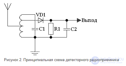
Figure 2. Schematic diagram of the detector radio
A single circuit with taps from an inductor is used as an input device in this circuit. The taps in the inductance coil are used to match the impedance of the circuit with the resistance of the antenna and the input resistance of the diode detector.

Comments
To leave a comment
Devices for the reception and processing of radio signals, Transmission, reception and processing of signals
Terms: Devices for the reception and processing of radio signals, Transmission, reception and processing of signals