When adjusting the input circuit with the resulting parameters to resonance at a certain frequency
 .
.
inductive resistance  and capacitive
  mutually compensated i.e. loop reactivity
  = 0,
= 0,
the resonant circuit has a purely active conductivity, and its value will be equal to 
 .
.
Voltage transfer ratio at the resonant frequency with (1)
 ,
,
 .
.
Where  - the modulus of conduction of the antenna;
 - resonant conductivity of the circuit with a quality factor
 - input active conductivity of the first stage of the receiver at a frequency f 0 ;
 - the active component of the conduction of the antenna.
The resonance gain varies with the coupling of the antenna with the input circuit, i.e. when changing the coefficient of inclusion (transformation)  . The choice of the coefficient
  in the circuit, a coordinated mode can be provided in which the antenna as a signal source gives the maximum possible nominal power to the receiver input. this mode is provided by choice
  equal to some matching value, equal to some matching value
  . To analyze the coordination mode, we write the expressions for
 where
where  .
.
If you change  and assuming the other parameters are constant, it can be seen that
  changes in two ways:
a) with increase  growing value
  because increases the voltage supplied from the antenna;
b) with increase  value
value  falls because An antenna increasingly shunts the circuit, as a result of which the resulting conductivity increases.
As a consequence of the specified joint action of these contradictory factors at a certain magnitude of the relationship  agreement occurs and the resonance gain reaches its maximum value.
For the max research we take the derivative
 .
.
and equate it to zero.
A study on the maximum shows that the matching value of the coefficient  equally
 ,
,  .
.
Then the resonant gain in matching
 .
.
Consider how the resonant gain changes with departure from matching. To do this, convert the expression for the resonant transmission coefficient as follows:
 ,
,
Where  - mismatch coefficient, which is understood as the ratio of the selected
  and matching
  values of the coefficient of inclusion (transformation).
In this way
 .
.
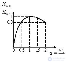
This dependence in relative units is
 .
.
Graphically, this dependence is shown in the figure.

Figure 6.4.
As can be seen from the figure, the maximum value of the transmission coefficient becomes  i.e. upon agreement. With significant waste from the negotiation mode within
  gear ratio does not change by more than 20%. As a result, where necessary, a departure from the negotiation mode is possible without a significant reduction in the transmission coefficient. In particular, the weak coupling mode
  and somewhat less is used to reduce the influence of antenna parameters on the bandwidth and tuning of the input circuit when the antenna parameters change significantly in the operating frequency range of the receiver.
Strong coupling mode  and a little more is sometimes used to provide the so-called optimal mismatch mode in order to reduce the noise figure.
It should be borne in mind that addiction  considered at a certain frequency
  input device settings.


Comments
To leave a comment
Devices for the reception and processing of radio signals, Transmission, reception and processing of signals
Terms: Devices for the reception and processing of radio signals, Transmission, reception and processing of signals