Lecture
The path for receiving and filtering radar signals includes a receiving device (PRU) and anti-interference devices (processing and filtering equipment), as well as an antenna and part of the high-frequency path involved in channeling the received signals from the antenna to the receiver.
The receiving device of radar signals performs the following main functions:
amplification of the useful signal with noise (interference);
selectivity (most often frequency) - the selection of a signal from the received mixture of signal and noise (interference);
amplification of the selected useful signal to a level that ensures the specified quality of processing and operation of terminal devices;
conversion of the useful signal, including frequency conversion;
demodulation of the useful signal (decoding).
The gain and selectivity functions are implemented at various frequencies: high ( f c), intermediate f CR = | f with - f g | and low linear conversion devices.
The functions associated with the transfer of the spectrum from one frequency range to another are implemented by non-linear devices in combination with linear filters of the high-frequency path.
Structural diagrams of the PRA are different depending on what functions, how and at what frequencies they are implemented. In radar, all radar receivers are usually built according to the superheterodyne type.
Fig.3.49 presents a generalized block diagram of the path for receiving and filtering radar radar signals. Elements of this scheme take place in any radar, although the path of a particular radar may not contain their full set. In radar, all radar receivers are usually built according to the superheterodyne type.
Building a prU on a superheginal scheme has several advantages. The fact is that at the intermediate frequency it is possible to provide a more stable and stable gain than at the microwave. In addition, the relative frequency band occupied by the useful signal at the intermediate frequency is larger, which allows for high selectivity over the adjacent channel and simplifies consistent filtering. It should be noted that the heterodyne frequency in the superheterodyne receiver can be changed after any change in the frequency of the transmitter without adjusting the intermediate frequency filters.
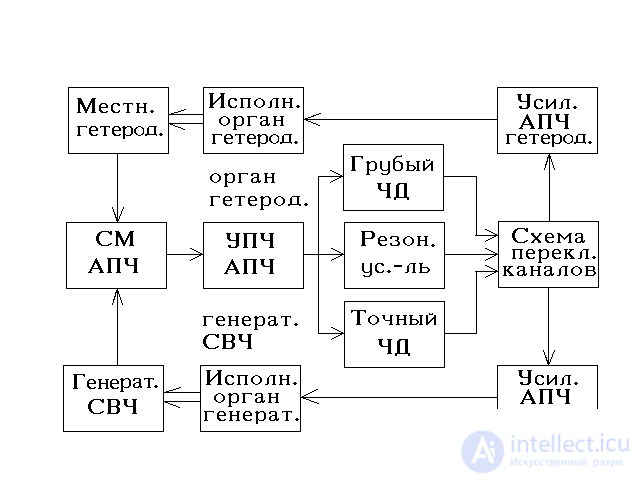
Fig.3.49. A generalized block diagram of the reception path and filtering radar radar signals.
UHF should provide such a level of internal noise receiving path, in which the total level of external and internal noise will be close to the minimum, determined only by external noise. It is practically enough to have a level of internal noise equal to the level of external noise, or several times (but not more than an order of magnitude) less than it. UHF is connected to the antenna with the help of passive elements united under the general name high-frequency path to receive or input circuits (feeder path).
The input circuit and UHF provide frequency preselection and signal preamplification. As preselectors, separate oscillatory systems or aggregates of several coupled oscillatory systems are used. At frequencies from 200 to 1000 MHz, segments of long lines are used as interstage chains, and at frequencies above 1000 MHz - cavity resonators, since here segments of long lines due to losses due to the surface effect do not have a high quality factor.
The frequency converter transfers the signal frequency spectrum to the intermediate frequency range. Its main parameters are the noise and power transfer coefficients affecting the sensitivity of the path, as well as the dynamic range of the signal input and the value of the intermediate frequency, affecting the degree of suppression of reception on the image channel and electromagnetic compatibility.
UHF and frequency converter strive to install in close proximity to the antenna feed (to avoid losses).
The main signal processing is performed at an intermediate frequency.
Matched filtering of single narrow-band echo signals is usually performed at the IFA, which is a multi-stage amplifier with linear filters that form the frequency response of the desired type. For sufficient pre-amplification of signals in power and coordination with a low-impedance load, special cascades of preliminary amplification of the intermediate frequency are used.
Equipment for protection against active noise interference - AZASHP performs automatic compensation of active noise interference at intermediate or video frequencies. The essence of the automatic compensation is that the aggregate of the noise interference and the useful signal received by the main antenna is automatically subtracted by the interference received by the additional weakly directed antenna overlapping the side lobes of the main antenna antenna pattern. Additional antennas, in general, may be several.
To ensure linear signal processing, measures are taken to expand the dynamic range of the HRO, for example, using AGC systems. The output voltage of the amplifier is usually fed to amplitude or phase detectors. The parameters of the detectors substantially depend on the amplitude of the detected signal. The limit value of the amplitude, starting from which the detector parameters become acceptable and stable, is 0.5-1 V, depending on the types of diodes used in the detector. Therefore, in addition to ensuring consistent filtering, UPCH also has the function of amplifying signals to the value necessary for the normal operation of the detectors.
Video Amplifier (VUS) is a broadband video amplifier, the bandwidth of which is matched with the spectrum of the amplified signal to the level necessary for normal operation of indicator devices and automatic signal detection equipment.
Protection equipment against passive interference - ARQP performs coherent processing of received signals. It can be implemented at an intermediate frequency or video frequency in order to extract useful signals against the background of passive interference. After detection, the output signals of the ARCS are fed to the switchboard, which, depending on the set operating mode, switches the signals of the amplitude and coherent channels.
The protection device against asynchronous impulse noise (NIP) performs suppression, as a rule, the blanking of the NPC at the video frequency.
The device combining the partial channels takes place in the receiving paths of the radar, forming several partial beams to receive, or in the radar with multi-frequency signals.
The energy of a pulse packet can be accumulated by switching from filters matched with individual pulses to comb filters matched with a periodic sequence of pulses. In the radar of the old park is usually used incoherent accumulation of video pulses. To do this, in the receiving path after the channel aggregation device or before it (in each channel) include the corresponding functional element - the non-coherent drive.
When using digital methods and devices for coherent signal processing at a video frequency, detection should be carried out in quadrature channels, which allows to obtain quadrature amplitudes
U c ( t ) = Re [ U ( t )] = u ( t ). Cos ( t ),
U s ( t ) = Im [ U ( t )] = u ( t ) .sin ( t ). physical signal (3.27)
U ( t ) = Re [ U ( t ) · exp ( f pr · t )] = u ( t ) · cos [2 f pr · t + ( t )].
The ratio of amplitudes (3.27) depends on the initial phase ( t ) of the signal (Fig. 3.50).
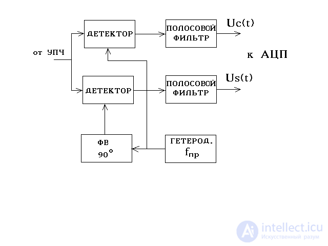
Fig.3.50. Detection scheme in quadrature channels.
In modern radars, the functions of protection against active and passive interference are assigned to digital anti-interference devices.
In modern radars, the receiving path can be built with the combined use of a linear and non-linear processing channel (Fig.3.51). The basis of the linear processing channel consists of the elements discussed above. As a rule, a nonlinear processing channel includes a limiter and a matched filter.
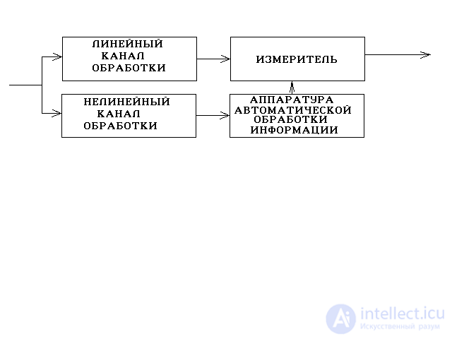
Fig.3.51. Linear and non-linear processing channels.
When the echo signal is detected, the automatic processing equipment issues a target indication pulse to the meter allowing the measurement of signal parameters. In such devices, when measuring the coordinates of air objects, linear processing channel information is used to improve accuracy.
In the nonlinear channel, measures are taken to stabilize the level of false alarms. The signals from the output of this channel are sent to the automatic target detection device.
Some features are inherent in superheterodyne receivers:
1. In tunable receivers, pairing (compatibility) of the input circuit, UHF, and local oscillator circuit settings is required. When working at fixed frequencies, this disadvantage disappears.
2. The presence of a frequency converter leads to the appearance of side reception channels: at an intermediate frequency; mirror; combinational channels; intermodulation.
The signal and oscillations of the local heterodyne (MG) simultaneously affect the mixer, which is a non-linear element. As a result, at the output of the mixer, a complex oscillation is obtained, containing components with a signal frequency f with, its harmonics 2 f with, 3 f with ..., components with f g and its harmonics with 2 f g, 3 f g ... and a large combinational components with frequencies:
f = | nf g + mf with |, m , n = 1,2, ...
Intermediate frequency f PR - one of the combination frequencies
f ol = | f g - f with |, with f pr < f c.
The mirror channel is formed at the frequency f fc = f g + f pr = f c + 2 f pr at f g> f c (at the upper setting of the local oscillator) and f cc = f g - f pr = f c - 2 f pr at f g < f with (at the lower setting of the local oscillator).
If this frequency is in the bandwidth of a preselector having a frequency response K pres ( f ), shown in Fig. 3.52, then a frequency is formed in the frequency converter, respectively.
f sk - f g = f pr, ( f g - f sk = f pr),
those. same frequency
f g - f c = f pr, ( f c - f g = f pr)
from the desired signal.
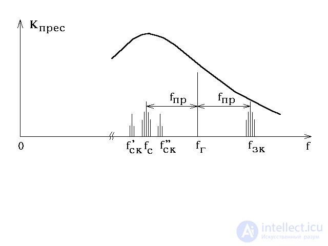
Fig.3.52. Side channels of reception.
Consequently, the spectra of the useful and interfering signals are superimposed, and the frequency filtering of the latter becomes impossible. There are two ways to weaken the effect on the image channel: by increasing the frequency selectivity of the preselector or by a higher intermediate frequency. In the latter case, the frequency of the mirror channel also increases, which makes it possible to better filter it in the preselector. However, the higher the intermediate frequency, the more difficult it is to ensure a high selectivity of IFCH with a bandwidth consistent with the width of the spectrum of the useful signal. To eliminate interference at the same time in the mirror and adjacent channels, multiple frequency conversion (reduction) is applied:
f PR1 = f G1 - f with; f pr2 = f r2 - f pr1.
Combinational reception channel is formed as a result of interaction between the combination frequencies of the local oscillator and the signal
f com = | nf g + mf with |, m , n = 1,2, ...
As a result, frequencies are formed close to f pr, i.e. included in the bandwidth of the HRO. Amplifying in the same way as a useful signal at a frequency f f , the combination components together with the frequencies of the signal at the detector output form beats ( f com- f f ). If they are included in the bandwidth of the low-frequency amplifier, then they are a disturbance reproduced further by the terminal device. The main measure to eliminate the combinational receive channel is to reduce the level of the harmonics of the local oscillator and the signal by selecting the operating mode of the mixer.
The intermodulation reception channel is formed when two or more interfering signals pass through the preselector at frequencies f 1 ... f i., Which in the mixer form signals with frequencies:
f in = n 1 f 1 + n 2 f 2 + n 3 f 3 + .... + n l f i,
where n 1, ... n i are integers.
The direct reception channel is formed when the interference has a frequency equal to the intermediate frequency and, acting on the frequency converter, passes without conversion to the IF amplifier channel. When designing a superheterodyne receiver, side channels can be practically eliminated by selecting the intermediate frequency, the mode of operation of the frequency converter, and the necessary frequency selectivity of the preselector and UPCH.
Thus, the general principle of constructing the reception paths and filtering the radar is the matching of their parameters with the parameters of useful radar signals. The harmonization conditions follow from the requirements for these paths, which generally boil down to ensuring a sufficient power level at the output, filtering quality of useful signals against the background of interference and ensuring the highest possible signal-to-noise ratio, subject to permissible distortions of those signal parameters that are used in the measurement process. .
Detector receiver
A superheterodyne radio receiver (superheterodyne) is one of the types of radio receivers based on the principle of converting a received signal into a signal of a fixed intermediate frequency (IF) and then amplifying it. The main advantage of superheterodyne to a direct gain radio receiver is that the most critical for reception quality parts of the receiving path (narrowband filter, IF amplifier and demodulator) should not be tuned to different frequencies, which allows them to perform with significantly better characteristics.
Superheterodyne receiver was invented by American Edwin Armstrong in 1918. 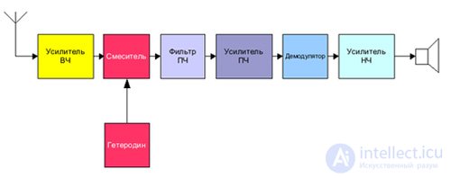
A simplified block diagram of superheterodyne is shown in the figure. The radio signal from the antenna is fed to the input of the high-frequency amplifier (in the simplified version it may be absent), and then to the input of the mixer - a special element with two inputs and one output that performs the signal frequency conversion operation. The signal from the local low-power high-frequency generator - the local oscillator is fed to the second input of the mixer. The oscillating circuit of the heterodyne is reconstructed simultaneously with the input circuit of the mixer (and the circuits of the RF amplifier) - usually a capacitor of variable capacitance (CLE), less commonly with a coil of variable inductance (variometer, ferrovarometer). Thus, at the output of the mixer, signals are generated with a frequency equal to the sum and difference of the frequencies of the local oscillator and the received radio station. A differential signal of a constant intermediate frequency (IF) is extracted using a concentrated selection filter (FSS) and is amplified by one or several stages, after which it is fed to a demodulator, which restores the low (audible) frequency signal. Usually, the IF filter is located in all stages of the intermediate frequency amplifier, because the FSS greatly attenuates the signal and brings it closer to the noise level. And in receivers with a filter with distributed selection in each stage, the signal is only slightly attenuated by the filter, and then amplified, which allows to improve the signal-to-noise ratio. Currently, a concentrated selection filter is used only in relatively inexpensive receivers made on integrated circuits (for example, K174XA10), as well as on televisions.
In conventional receivers of long, medium and short waves, the intermediate frequency is usually 465 or 455 kHz, in ultrashort waves - 6.5 or 10.7 MHz. TVs use an intermediate frequency of 38 MHz. Since the superheterodyne receiver is well tuned to a signal with an intermediate frequency, even a weak signal at that frequency is received. Therefore, the intermediate frequency is used to transmit SOS signals. At these frequencies, the work of any radio stations in the world is prohibited.
Benefits
 For example, if the input is tuned to a radio station transmitting at 70 MHz and the local oscillator frequency is 76.5 MHz, the output of the IF filter will be a normal signal with a frequency of 6.5 MHz. However, in the presence of another powerful radio station at a frequency of 83 MHz, its signal can also leak to the mixer input, and the difference signal with a frequency of 83 - 76.5 = 6.5 MHz will not be suppressed either. В таком случае приём сопровождается различными помехами. Избирательность по зеркальному каналу зависит от добротности и числа входных контуров. При двух перестраиваемых входных контурах требуется трёхсекционный конденсатор переменной ёмкости (КПЁ), что дорого.
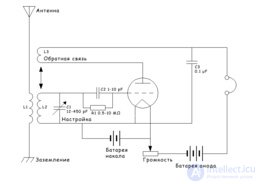
 Регенератор позволяет получить наибольшую отдачу от одного усилительного элемента. Поэтому в ранние годы развития радиотехники, когда лампы, пассивные детали и источники питания были дороги, он широко применялся в профессиональных, любительских и бытовых приёмниках, успешно конкурируя с изобретённым в 1918 г. тем же Армстронгом супергетеродином.
  Отсюда видно, что при увеличении обратной связи коэффициент регенерации M и добротность могут стремиться к бесконечности, но их практический рост ограничен стабильностью параметров схемы - если изменение коэффициента усиления будет больше 1 / M, то регенератор либо сорвётся в генерацию (если усиление выросло), либо потеряет половину чувствительности и избирательности (если усиление упало).
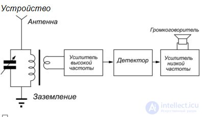


Comments