Lecture
The purpose of the analysis.
In the analysis of the inverter solve two main tasks:
1) determine the input voltage  Why find a useful component of the current
  intermediate frequency, which coincides with the resonant frequency of the filter, and then calculate the main indicators of the converter - gain, frequency response, phase response, etc .;
2) find the component of the inverter input current at a frequency  that loads the signal source.
To simplify the analysis is carried out under the following assumptions:
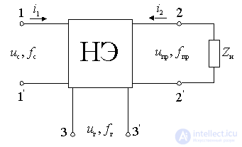
a) The mixer of any frequency converter is considered as a non-linear six-port circuit, the output of which includes a selective load  tuned to intermediate frequency.

Figure 11.3.
b) We assume that three harmonic voltages act on a nonlinear element:
- signal voltage  ;
;
- intermediate frequency voltage  ;
;
- the voltage of the local oscillator  .
.
c) We believe that  and
and  i.e. we assume a nonlinear element operating in a linear mode with respect to the signal voltage; relative to the voltage of the heterodyne, the nonlinear element always operates in a nonlinear mode.
d) We assume that the nonlinear element of the mixer is a spinless device that does not contain capacitive and inductive elements. Therefore, its current does not depend on the derivatives or integrals of the voltages applied to the nonlinear element. For inertia-free NE, the input and output currents are determined by the static current-voltage characteristic:
 ,
,
 .
.
Determination of the useful component of the output current (direct frequency conversion).
Because  and
and  small then current

can be decomposed into a Taylor series in two variables, by limiting the number of members with  and
and  in the first degree:
 . (**)
The first term is a component of the output current, which is caused by the action of the heterodyne voltage at  . We introduce the notation
 .
.
Second term  characterizes the input current increment, which is caused by the action of the signal.
 - the instantaneous value of the direct conduction or the steepness of the non-constant periodically varying in time under the action of the voltage of the local oscillator.
Third term  is the increment of the output current of the mixer as a result of the action of the intermediate frequency voltage at its output.
 - the instantaneous value of the output conductivity of the mixer, changing in time under the action of the voltage of the local oscillator.
According to the linear theory of frequency converters, the first three terms are taken into account in the expression (**); at the same time current  linearly dependent on
  and
and  . Taking into account the accepted notation, you can write
 .
.
Since the magnitudes  ,
,  and
and  are determined when there is a local oscillator voltage and periodically with a frequency
  vary in time, they can be represented by Fourier series:
 ;
;
 ;
;
 .
.
The obtained series contain only cosine terms, since  , and we consider non-inertia.
Substituting the resulting relations in the expression for  , we get:
 .
.
or using the cosine multiplication rule, we get
 . (*)
. (*)
It is clear from the last two relations that the output current of the mixer contains components with frequencies  and combination components with frequencies
 and
and  .
.
Frequency conversion is possible on any harmonic of a slope:
 ;
;
 at
at  ;
;
 at
at  .
.
Of these values, only one is used. If at 
 , the frequency conversion is called simple. If at
 , the frequency conversion is called Raman, it is possible because of the appearance of harmonics of the slope.
Thus, of all the components of the output current, only the component with the frequency  .
.
We define in the expression (*) the current component with frequency  . Due to the second term with
  and the third term at
  will have
 ;
;
or
 . (-)
. (-)
Turning to the complex amplitude, this expression can be written
 (+)
(+)
Where  ;
; 
This relationship is called the direct frequency conversion equation. The first term of the equations (-) and (+) characterizes the process of frequency conversion. The second term is due to the load response, since  depends on load resistance
  .
.
Determination of the useful component of the input current (inverse frequency conversion).
In the mixer, along with direct and possibly reverse frequency conversion. Its physical meaning is that if an intermediate frequency voltage is applied to the input terminals of the mixer, then if there is a heterodyne voltage, a current with a signal frequency will flow through the input terminals of the mixer. Such frequency conversion is possible only if the mixer has nonlinear inverse-conductivity, periodically changing with the frequency of the local oscillator. Inverse frequency conversion changes the input and output conductance of the mixer. this is most pronounced in the diode frequency converter.
The inverse frequency conversion equation can be obtained by representing the input current  as a function of the local oscillator voltage
  and two small variables
  and
and  .
.
 .
.
By expanding this function in a Taylor series in two variables  and
and  . and limited to linear members, get
 .
.
Where  - the current at the input of the ne due to the action of the voltage of the local oscillator;
 - the instantaneous value of the input conductance NE;
 - instantaneous value of the conductance of the feedback NE.
Acting as in the case of direct frequency conversion, in the end, for the reverse frequency conversion, you can get
 ,
,
Where  - amplitude of the kth conduction harmonic of the inverse transform
  for intermediate frequency voltage;
 - constant component of input conductance
  for voltage signal.
Internal parameters of the frequency converter.
Based on the equations of direct and inverse transformations, we define the internal parameters of the converter, i.e. Parameters independent of load impedance and source impedance.
a) Direct-acting internal conductivity (direct conversion slope) is defined as the ratio of the amplitude of the intermediate-frequency current to the amplitude of the voltage of the input signal with a shorted output (  ):
):
 ;
;
b) The internal output conductance of the converter is equal to the ratio of the amplitude of the intermediate frequency current to the amplitude of the voltage of the same frequency with a short-circuited input (  ):
):
 ;
;
c) Internal conduction of the reverse action (steepness of the inverse transformation  ) is calculated as the ratio of the amplitude of the current component to the frequency of the signal to the amplitude of the intermediate-frequency voltage with a short-circuited input (
  ):
):
 ;
;
d) Internal input conductance is equal to the ratio of the amplitude of the current component with the frequency of the signal to the amplitude of the voltage of the same frequency, with shorted output terminals (  ):
):
 .
.
In the general case, with the inertial nature of the conductivity of the nonlinear element, the internal parameters of the mixer are complex quantities. Therefore, the equations characterizing the operation of the mixer should be written in the form:
 .
.
Thus, the transforming element together with the local oscillator can be represented as a quasilinear quadrupole, characterized by four y-parameters — the transforming parameters.
External parameters of the converter.
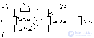
Equivalent equivalent circuits of amplifying elements of the amplifying and converting cascades do not outwardly differ. The difference is only in the value of the parameters. Therefore, similarly to the amplifying (resonant) cascade, we define the external parameters of the converter.

Figure 11.4.
a) Gain
 .
.
b) input conductance
 .
.
c) output conductivity
 .
.
Where  - signal source conductivity;
 - load conductivity.
Comments
To leave a comment
Devices for the reception and processing of radio signals, Transmission, reception and processing of signals
Terms: Devices for the reception and processing of radio signals, Transmission, reception and processing of signals