Lecture
During phase modulation, the amplitude of the carrier collar *** of U 0 is kept constant, and the phase of the carrier collar *** of φ (t) is associated with the modulating voltage e (t)
ψ (t) = ω 0 t + k FM e (t) + φ 0 , (5.12)
where k FM is the proportionality coefficient, which determines the relationship between the modulating voltage e (t) and the additional increment of the total phase of the resulting phase-modulated colo ***.e (t) = E cos (´Ωt + Θ)
the full phase of the phase-modulated col ration takes the valueψ (t) = ω 0 t + k FM E cos (Ωt +) + φ 0 (5.13)
The maximum additional deviation of the phase of the carrying colum *** with respect to the regular value of ω 0 t is characterized by the phase modulation index M FM :M FM = k FM E. (5.14)
Thus, a complete description of the phase-modulated *** dialing modulated by the tone signal has the form:u FM (t) = U 0 cos [ω 0 t + k FM E cos (´Ωt + Θ) + φ 0 ] . (5.15)
Timing diagrams of the modulating and carrier signals, as well as the phase-modulated colo *** are shown in Figure 5.5.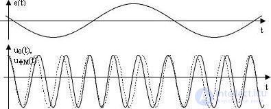
Fig. 5.5 Phase Modulation:
a) modulating signal; b) carrier ring *** (dashed line) and phase-modulated ring *** (solid line)
u FM (t) = U 0 cos [ω 0 t + M FM cos´Ωt].
u FM (t) = U 0 cos (ω 0 t) х cos (M ФМ cos´Ωt) - U 0 sin (ω 0 t) sin (M ФМ cos´Ωt) . (5.16)
Due to the smallness of the argument (M FM cos´Ωt << 1) of the trigonometric functions cos (M FM cos´Ωt) and sin (M FM cos´Ωt), the approximate relations cos (M FM cos´Ωt) ~ 1 and sin (M FM cos´Ωt) ~ M FM cos´Ωt. Taking into account these approximations, expression (5.16) is reduced to the form:
u FM (t) = U 0 cos (ω 0 t) - (U 0 M FM / 2) cos (ω 0 - Ω) t + (U 0 M FM / 2) cos (ω 0 - Ω) t . (5.17)
In terms of its form, expression (5.17) for phase-modulated wheels *** with M FM << 1 resembles the expression for amplitude-modulated wheels *** *** (5.5): carrier ring *** with frequency ω 0 and amplitude U 0 and two side components with the same amplitudes equal to U 0 M A / 2 and frequencies equal to (ω 0 - ´Ω) and (ω 0 + ´Ω). The difference in the composition of the spectra of amplitude-modulated and phase-modulated col ues *** lies only in the fact that in these col ods, the components with a frequency equal to (ω 0 - ´Ω) have opposite signs. The frequency band occupied by the phase-modulated signal in this case is also equal to
P FM ~ 2 ´Ω . (5.18)
For large phase modulation indices (M FM << 1), the dependence between the frequency bands occupied by the modulating and phase-modulated signals obeys more complex expressions than, for example, the relation (5.18).

Comments
To leave a comment
Devices for the reception and processing of radio signals, Transmission, reception and processing of signals
Terms: Devices for the reception and processing of radio signals, Transmission, reception and processing of signals