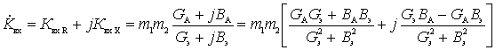
Based on the obtained equivalent circuit, for the voltage at the output of the circuit can be written:
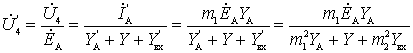
Then the transfer coefficient of the input device:
Where 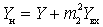 - the conductivity of the load is equal to the sum of the conductivity of the circuit and the recalculated conductivity of the input of the first cascade;
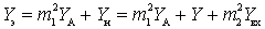 - the resulting conductivity of the circuit, taking into account the conductivities introduced by the antenna-feeder system and the input of the first cascade.
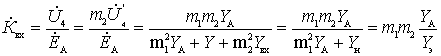
From the resulting expression for  it follows that the transfer coefficient depends on the inclusion (transformation) coefficients at the input m 1 and output m 2 of the electoral system, as well as the relationship of conductances
  antennas as signal source and resulting conductance
  input device.
Included in the expression for magnitude varies with frequency within each sub-band relatively slowly. Resulting conductivity has a pronounced minimum at the resonant frequency of the parallel circuit. Assuming that  and
and  real numbers, independent of frequency, the transfer coefficient has a maximum that almost coincides with the natural frequency of the input circuit with the resulting parameters. We define the module angle of phase shift of the transmission coefficient. For this expression for we will present in the following form:
 .
.
Transmission Ratio Module
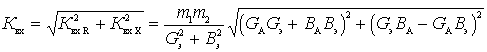 . (one)
Phase angle
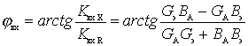 .
.
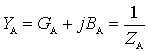
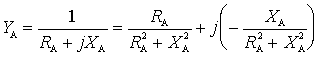
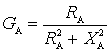
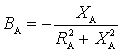
Active value  and reactive
  the conductivities of the antenna with its given parameters
  and
and  are determined by considering that
 , but
, but 
Then
 .
.
those.
 .
.

Comments