The schematic diagram .
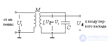
Figure 7.1.
A contour is used as a frequency-selective system.  tunable or by changing capacitance
  or feeder joins connection coil
  .
.
and  an electromagnetic coupling is performed, characterized by the coefficient of mutual inductance kcv . The value of ksv is determined by the coupling between the coils. and determined by the coupling coefficient
The choice of communication determines the possibility of transmitting the energy of the signals from the antenna to the circuit and the effect of the antenna on the bandwidth and tuning of the circuit.
The choice of coupling coefficients is limited by the possibilities of constructive implementation of the associated system. For example: -  for the simplest single-layer coils; -
  for multilayer coils.
Choice of inductance You can influence the antenna circuit settings by shifting it to the lower boundary of the subband and obtaining the falling character of the gain change or shifting it to the upper boundary of the subband and getting the gain dependence increasing with frequency.
Equivalent scheme .
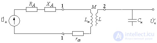
Figure 7.2.
Loop parameters are represented by inductance  capacity
  and resistance
  , taking into account the losses in the circuit and the influence of the input of the first cascade. Communication with the antenna is estimated by the transformation ratio.
 ,
,
Where  and
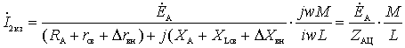
and  - short-circuit currents of the terminals 11 'and 22'.
These currents can be found as follows:
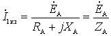 ;
;
 ,
,
Where  ;
;
 ,
,  ,
,
and introduced resistances due to their relative smallness can be neglected.
Then the inclusion ratio (transformation):
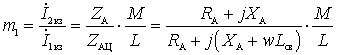 .
.
In the unconfigured antenna mode, when  , the coefficient of inclusion (transformation):
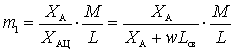 .
.
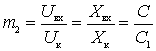
In many sources, the coefficient of inclusion  defined as
  .
.
Obviously for the high frequency region can be considered  and then
  .
.
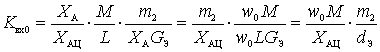
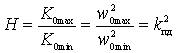
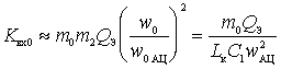
Resonance gain .
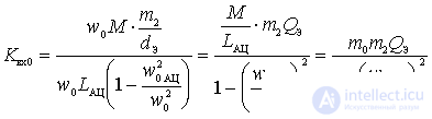
As determined in the analysis of a single-circuit input circuit, the resonance transfer coefficient of the input circuit is determined by:
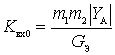 or
or 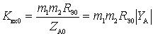 .
.
If in this expression to substitute the value  and take into account also that at relatively high frequencies
  those.
 or
or  .
.
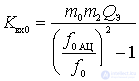
Then
 .
.
If we assume that within each subrange  and
and  change insignificantly, it is clear that the change
  is determined by the nature of the dependence on the frequency parameters of the antenna circuit
  and bond resistance
  .
.
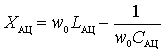 ,
,
Where  - inductance of the antenna circuit;
 - capacity of the antenna circuit;
 - natural frequency of the antenna circuit;
 - natural frequency of the input circuit.
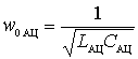
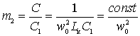
Imagine in the following form:
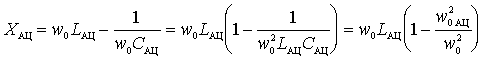 .
.
Then
 ,
,
 - some constant coefficient characterizing the connection with the antenna and is called the communication parameter. From the last expression it is seen that the change in the resonant transfer coefficient of the input circuit will be different depending on the ratio
  .
.
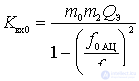
Possible modes of operation of the input circuit .
but) The first case . The natural frequency of the antenna circuit is above the upper frequency of the working sub-band, i.e.  .
.
This is the so-called mode with increasing the natural frequency of the antenna circuit or the mode with a "shortened" antenna.
The transfer coefficient is presented in the form:
 .
.
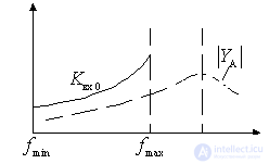
Figure 7.3.
In this mode, the transmission coefficient increases dramatically with frequency, because with increasing frequency simultaneously increases  and
and  due to the approach frequency tuning of the input circuit to the resonant frequency of the antenna circuit.
With  expression for
  can lead to the following form:
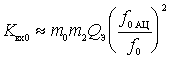 .
.
If a  and if
  then
then

(+) The unevenness of the transmission coefficient across the sub-band:
 .
.
The conditions for which the expression (+) is obtained are characteristic for the connection of the circuit with the input of lamps and field-effect transistors (  ). In circuits with bipolar transistors
  and often
  dependent on frequency. For example, consider the internal capacitive coupling of the circuit to the input of the first cascade.
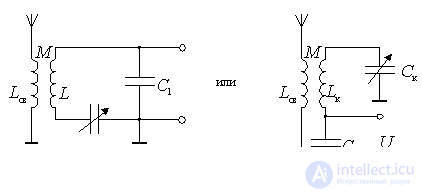
Figure 7.4.
 ;
;
 .
.
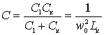
In the circuit with the internal capacitive coupling of the circuit with the active element, the switching coefficient is:
 .
.
If you substitute in the expression for  , we get:
 .
.
From this expression it is clear that the change the subrange is possible mainly due to a change in the equivalent quality factor  .
.
 .
.
Input circuit attenuation with the antenna turned off
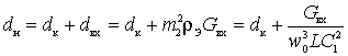 .
.
This shows that with increasing frequency  decreases as well increases. This is useful for keeping the contour's selective properties unchanged within the subrange. b) The second case . The natural frequency of the antenna circuit is below the minimum frequency of the working subrange
  . This is the so-called mode of lowering the frequency of the antenna circuit or the mode with the "elongated" antenna. The resonance transfer coefficient does not change as dramatically as in the previous case, since when moving away from the natural frequency of the antenna circuit quantities
  decreases a
  increases and to some extent compensates for the decrease .
The transfer ratio can be represented as:
 .
.
With  You can write:
 .
.
If a and then
 . (*)
. (*)
The conditions under which the expression (*) is obtained are characteristic of circuits on lamps and field-effect transistors (with  ). In circuits with bipolar transistors frequency dependent due to insertion loss
  . And if frequency independent coefficient, then the quality factor falls with increasing frequency. therefore in the expression (*) will not be constant, but will decrease with increasing frequency.
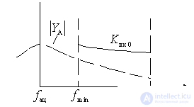
Figure 7.5.
at) The third case .  i.e. The natural frequency of the antenna circuit is in the working frequency range of the receiver.
In this mode, the transmission coefficient is highly dependent on frequency, so this mode is usually not used.

Comments
To leave a comment
Devices for the reception and processing of radio signals, Transmission, reception and processing of signals
Terms: Devices for the reception and processing of radio signals, Transmission, reception and processing of signals