Lecture
As we already know, the local oscillators in the receivers are designed for use as part of mixers to transfer the spectrum of the input signal to a lower frequency. The quality of the converted signal and, in general, the parameters of the entire receiving device as a whole depend on the parameters of the local oscillators.
The main parameters of the local oscillator:
The operating frequency or frequency range is determined based on the frequency band of the received signal. For example, for the GSM standard 900, the range of received frequencies for mobile devices is 935 ... 960 MHz. With a nominal intermediate frequency of 45 MHz, the operating frequency range of the local oscillator will be equal to 980 ... 1005 MHz.
The step of rebuilding the local oscillator is set by the width of the radio channel adopted in the communication system in which the receiver will operate. For example, the heterodyne restructuring step for the GSM cellular standard will be 200 kHz.
The output power of the local oscillator (in dBm) is determined on the basis of the required power for the mixer, plus a margin of 2 ... 4 dB required to compensate for losses in the path of the local oscillator-mixer and the error on the input of the mixer. Typically, the level of the local oscillator signal is +16 dBm.
Relative frequency instability is a characteristic showing the deviation of the generator frequency (frequency drift) from the nominal value. This value is determined by the ratio
 ,
,
Where  - frequency drift,
f 0 is the nominal frequency.
There are short-term (for example, for 1 second) and long-term (for example, for 1 year).
Let for 1 year the drift frequency of a local oscillator with a nominal frequency of 10 GHz is 1 kHz. Then the long-term relative frequency instability will be equal to:
103/1010 = 10-7
There is another way to set the frequency instability. Let the temperature instability in the temperature range (-40 C0 ... +50 C0) be set as follows: +1 ppm / C0, where ppm means a millionth part of the whole. Then the temperature frequency drift for a local oscillator with a frequency of 10 GHz will be:
+1 ppm / C0 x 1010 Hz = + 10-6 / C0 x 1010 = 10 kHz / C0,
while the relative frequency instability will be equal to:
104/1010 = 10-6
Frequency drift as the supply voltage changes (pushing) can be minimized by using voltage stabilizers.
To reduce the relative frequency instability due to load changes (pulling) at the output of the local oscillator, decoupling devices (valves) or buffer amplifiers are used, which also provide the required local oscillator power.
The accuracy of the frequency setting is set by the resonant frequency of the resonator in the feedback circuit of the generator. In the case of using a frequency synthesizer as the local oscillator, the accuracy of setting the local oscillator frequency is determined by the frequency of the reference oscillator. Usually this value is 10 ... 1000 Hz.
The relative level of harmonics at the output depends on the generator circuit and the presence of a filter at its output. Usually, the output of the local oscillator requires that the level of harmonics does not exceed -25 dB.
The spectral power density of the phase noise characterizes the short-term phase instability of the LO frequency due to the noise properties of the generator.
The factors listed above lead to the fact that in the spectrum of the output signal of the local oscillator we see not a single frequency component, as we would like, but a whole spectrum. An example of the spectrum of the local oscillator is shown in Figure 1.
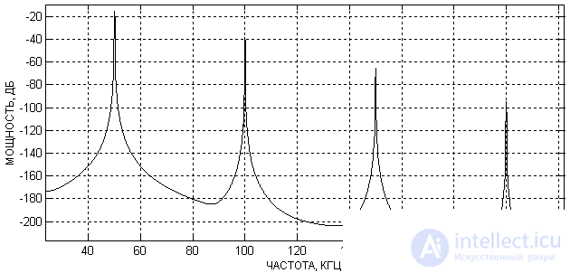
Figure 1. LO Spectrum Output Spectrum
It should not be assumed that the signal of the local oscillator in the time domain will be greatly distorted. Figure 2 shows the timing diagram of the signal, the spectrum of which is shown in Figure 1.
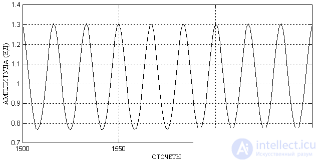
Figure 2. Timing diagram of the output of the local oscillator
As can be seen from this figure, the shape of the output oscillation of the local oscillator practically does not differ from the sinusoidal one. Therefore, when assessing the quality of the output signal of a local oscillator, its spectrum is usually considered.
As already discussed when studying the characteristics of the mixer, the local oscillator harmonics under certain conditions do not affect the transfer of the spectrum of the received signal to the intermediate or zero frequency. In addition, they can be easily filtered. Therefore, in the future, we will mainly evaluate the noise characteristics of the local oscillator and its instability.
An important mechanism that limits the dynamic range of the receiver is the conversion of the local oscillator noise to the intermediate frequency path (Reciprocal mixing). An example of the distribution of the noise density of the local oscillator depending on the detuning from the generated frequency is shown in Figure 3.
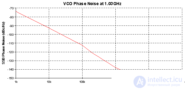
Figure 3 - Dependence of the heterodyne noise on the detuning from the generated frequency for the ADF4360-7 chip.
This figure shows the dependence calculated by the ADIsimPLL program for the ADF4360-7 frequency synthesizer. The Y axis represents the noise density with respect to the fundamental harmonic of the local oscillator on a logarithmic scale:
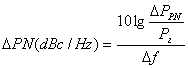
where P PN is the phase noise power of the local oscillator;
P g - the signal power at the output of the local oscillator.
In a real scheme, due to the non-ideality of the structure and power sources, the noise density of the local oscillator in the far-field zone may turn out to be even worse.
The phase noise of the local oscillator is no different from the oscillations at the tuning frequency of the synthesizer. When interacting with it, the interference signal is converted to an intermediate frequency, but since the conversion is performed with a noise signal, the result is perceived as noise.
This phenomenon leads to a deterioration of the signal-to-noise ratio at the output of the receiver. Thus, the used local oscillators must have such a low phase noise that, in the presence of strong out-of-band interference, they create noise that is less than the noise level of the receiver.
продолжение следует...
Часть 1 Heterodyne 1 parameters of the local oscillators

Comments