Lecture
The higher the frequency of the received useful signal, the less the relative detuning of the image channel is obtained for the same value of the intermediate frequency. As a result, when implementing a high frequency superheterodyne radio receiver, a contradiction arises between the requirement to reduce the intermediate frequency to facilitate the suppression of the adjacent channel in the intermediate frequency path and the requirement to increase the intermediate frequency to facilitate the suppression of the mirror channel in the preselector. In this case, double frequency conversion is used.
In the case of double frequency conversion, first transfer the group of channels to the first intermediate frequency, allocate it, and then allocate the working channel at the second intermediate frequency. This process is illustrated by the frequency diagram shown in Figure 1.
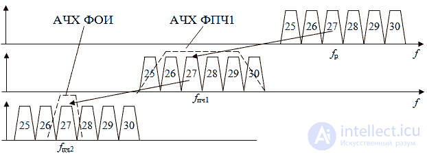
Figure 1 Transfer spectrum of the working channel with double frequency conversion
In this figure, the useful signal with frequency f p is first transferred to the first intermediate frequency f f1. The value of the first intermediate frequency is chosen large enough to facilitate the suppression of the mirror channel f by the filter of the preselector.
At the first intermediate frequency f b1 it is impossible to provide suppression of the adjacent channel, therefore, the gain of the path of the first intermediate frequency is attempted to be minimally necessary, just not to increase the noise level at the receiver output. The main objective of the path of the first intermediate frequency is to suppress the mirror channel f hv2, which is formed in the second mixer. The amplifier UPCH1 only compensates for the losses in the filter FPCH1 and, if necessary, the loss of the mixer.
The block diagram of a superheterodyne receiver with double frequency conversion is shown in Figure 2.
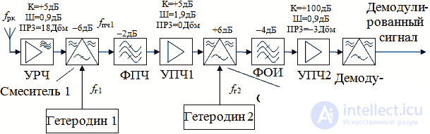
Figure 2 Block diagram of a superheterodyne radio receiver with double frequency conversion
In the double-frequency tunable superheterodyne circuit, only the first local oscillator is executed. As such a local oscillator, a discrete frequency grid synthesizer is usually used. The second local oscillator can be performed at a fixed frequency. This allows the intermediate frequency filter FPCH1 to implement at a fixed frequency, thereby simplifying its implementation.
In the scheme of a superheterodyne receiver with double frequency conversion, it is necessary to calculate the parameters of each unit just as carefully as in the previously considered scheme of a superheterodyne receiver. Due to the fact that the requirements for the dynamic range of the second frequency converter are lower than the requirements for the first mixer, the second frequency converter can be performed on transistors according to the mixer circuit with suppression of the mirror channel.
When receiving digital signal types, it is necessary to take into account the position of the frequency of the first and second local oscillators (higher or lower than the frequency of the input signal), since this can lead to a change in the direction of rotation of the quadrature vector.
In some narrow-band receivers with a sufficiently high carrier frequency, in some cases, it is necessary to use not only double frequency conversion, but also triple. At the same time, the principles of forming requirements for additional blocks do not differ from those considered earlier for a superheterodyne receiver with double frequency conversion.

Comments
To leave a comment
Devices for the reception and processing of radio signals, Transmission, reception and processing of signals
Terms: Devices for the reception and processing of radio signals, Transmission, reception and processing of signals