Lecture
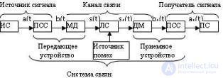
The set of technical means for transmitting messages from the source to the consumer is called a communication system. Obligatory components of any communication system, regardless of the type of transmitted messages, are the transmitting device, the communication line and the receiving device. Sometimes the term “communication system” includes the source and consumer of messages. A generalized block diagram of a communication system is shown in Fig. 3.2. The message a (t) from the source of the IC of messages arrives at the transmitting device consisting of the primary converter PSS1 of the message into the primary electrical signal b (t) and the modulator MD providing the secondary conversion of this signal into the signal s (t) for its best transmission over the line communication. A LAN connection line is the medium used to transmit signals from the transmitter to the receiver (cable, waveguide, or a region of space in which electromagnetic waves propagate from the transmitter to the receiver).

Fig. 3.2 Generalized block diagram of a communication system
The receiving device performs the inverse transformation of the received signal into the message and consists of a demodulator DM and a converter of the MSS signal into the message. The differences in the parameters of the communication system from the desired characteristics lead to distortions of the transmitted signal. In addition, in any node of the transmission system, but mainly on the communication line, there is interference, therefore the signal at the input of the receiver s1 (t) differs from the transmitted signal at the output of the transmitter. The receiving device processes the received col. *** and restores the electrical signal b1 (t), and, consequently, the message a1 (t), which is restored with some error.
A communication system is called multichannel if it provides for the transmission of several messages over one common communication line (Figure 3.3). Each of the transmitted messages using MSS converters is converted into separate electrical signals, which are then mixed in the compaction equipment (AU). The group signal formed in this way and processed additionally in the transmitting device MD is transmitted via the communication line. The receiver performs the inverse transformation of the received *** ring to the original group signal, from which individual signals (converted into the corresponding messages in MSS converters) are then separated out using a separation device (RR).

Fig. 3.3 Block diagram of a multi-channel communication system
In order to separate the transmitted signals at the receiving end, it is necessary that they differ from each other by some attribute. In the practice of multichannel communication, frequency and time signal separation methods are mainly used. With frequency division channels, each of the individual signals is allocated a separate frequency range in the total frequency band. During time division of the channels, each of the communication channels is allocated a certain time interval in each cycle of transmitting the collective signal. Recently, the method of code division of channels is becoming more widespread. With this channel separation, all channels can simultaneously occupy a common frequency and time resource of a communication system. To separate the channels in this case, the separation of channels by waveform is used (in digital communication systems, by the code of signals).
Comments
To leave a comment
Devices for the reception and processing of radio signals, Transmission, reception and processing of signals
Terms: Devices for the reception and processing of radio signals, Transmission, reception and processing of signals