Lecture
Satellite communication systems can be considered as a special type of radio-relay communication lines if the antenna of the repeater is suspended on a support whose height is equal to the height of the satellite orbit. In such a communication system, the area of direct visibility of the Earth’s surface viewed from the satellite and, accordingly, the size of the earth’s territory from which the satellite is visible at the same time instantly increases.
Radio equipment of a satellite communication system located on a satellite is called a space radio station, and radio equipment located on Earth is called a ground radio station. The channel of radio transmission from the ground station to the satellite is called upstream, and the channel of transmission of signals in the opposite direction - downstream. On the satellites, in addition to the relay equipment, also place power supplies (solar panels). In addition, the satellites have the equipment to stabilize the position of the satellites in orbit and orient it in space (the repeater antennas are directed toward the Earth, the solar panels towards the Sun).
The characteristics of satellite communication systems largely depend on the parameters of the satellite orbit. The satellite orbit is the trajectory of the satellite in space.
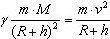
The physical body goes into a circular orbit around the Earth and becomes its satellite if it is informed of the first cosmic velocity. In this case, the centripetal force equal to the gravitational pull of the satellite is balanced by the centripetal force determined by the satellite’s linear velocity v and the distance between the centers of mass of the Earth and the satellite equal to R + h, where R is the radius of the Earth, h is the height of the satellite above the Earth’s surface. Without taking into account other factors affecting the behavior of the satellite in orbit, the equation of state of the dynamic equilibrium of the satellite has the form:
 (8.2)
(8.2)
For heights significantly smaller than the Earth’s radius (h << R), expression (8.2) simplifies:
mg ∼ mv² / R, (8.3)
where g = γM / R² 9.81 m / s² is the acceleration of free fall at the Earth's surface.The speed necessary for a moving body to become a satellite of the Earth is determined from the relation (8.2):
 (8.4)
(8.4)
The first cosmic velocity at the Earth's surface (h ∼ 0), according to (8.3), (8.4) is equal to
 km / s (8.5)
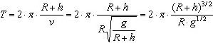
The orbital period of a satellite around the Earth, taking into account the expression (8.4), is defined as
 (8.6)
(8.6)
Graphs of the linear velocity of the satellite in a circular orbit and the period of the satellite’s orbit around the Earth versus the orbit altitude above the Earth’s surface are shown in Fig. 8.6. More accurate formulas of satellite motion take into account the influence of other factors (the difference between the shape of the Earth and the spherical one, the attraction of the Moon, the Sun and other celestial bodies, etc.).
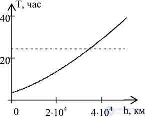
Fig. 8.6 Dependence of the orbital period of a satellite around the Earth on the height of the orbit
If the satellite is reported to have a speed greater than the first cosmic one, then it will move in an elliptical orbit. The speed of the satellite when moving in an elliptical orbit continuously changes from the lowest value at the point of maximum distance from the Earth (apogee) to the maximum value at the point of closest approach to the Earth (perigee).
Orbits can pass in any direction around the globe, but the orbit plane will pass through the center of the Earth. Orbits can be classified by various attributes.
Orbits are distinguished by the relative position of the orbital plane of the satellite and the plane of the Earth’s equator. If the satellite's orbit plane coincides with the Earth's equatorial plane, then the satellite's orbit is called equatorial. An orbit is called polar if the plane of the satellite’s orbit passes through the poles of the Earth. The orbit is called oblique for other mutual arrangements of the plane of the satellite orbit and the plane of the Earth's equator.
Orbits can be circular with the center of a circle located in the center of the Earth, or elliptical, while the center of the Earth is in one of the foci of the ellipse. In addition, the orbits also differ in height above the Earth’s surface.
The satellite, located in the equatorial orbit, at an altitude of about 36 thousand kilometers from the Earth's surface, has unique properties. The orbital period of the satellite at this height coincides with the period of the Earth’s rotation around its axis. If a satellite is launched into such an orbit in the direction coinciding with the direction of rotation of the Earth, then such a satellite will appear stationary relative to the surface of the Earth. A satellite in such an orbit is called geostationary.
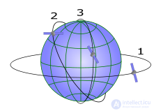
To build satellite communication systems, three types of orbits are mainly used: a geostationary orbit, a high elliptical orbit, and a low-altitude orbit. Approximate diagrams of these orbits are shown in Figure 8.7.
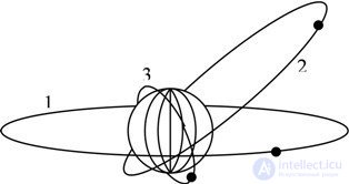
Fig. 8.7. Orbits of Earth satellites: 1 — geostationary; 2 - high elliptical; 3 - low-altitude
The area of the earth's surface on which satellite ground stations can be located is called a service area. The characteristics of the communication system are determined by the position of the satellite in orbit. One of the important parameters of satellite communications is the angle of elevation of a satellite for an earth observer - this is the angle between the direction of the satellite and the tangent to the circle at the location of the earth station.
Satellite communication is one of the types of space radio communications, based on the use of artificial satellites as repeaters. Satellite communication is carried out between earth stations, which can be both stationary and mobile.
Satellite communication is the development of traditional radio-relay communication by bringing the repeater to a very high altitude (from tens to hundreds of thousands of km [ source not specified 551 days ] ). Since its zone of visibility in this case is almost half of the globe, the need for a chain of repeaters disappears - in most cases one is enough.
The mutual arrangement of the Earth and the satellite is shown in Figure 8.8.
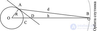
Fig. 8.8 The relative position of the Earth and the satellite
An essential feature of satellite communications is the delay in the propagation of signals caused by the passage of fairly large distances. This delay varies from a minimum value when the satellite is at its zenith, to a maximum value when the satellite is on the horizon line. For the triangle ABO, shown in Figure 8.8, the following relationship holds true:
sin (∠OAB) / OB = sin (∠AOB) / AB (8.7)
Considering that the angle ∠OAB = ∠AOD + ∠DAB , and the angle OAB = π / 2 (AD is the tangent to the circle at point A) and, denoting the segments: AB is the distance from the satellite to the earth station (| AB | = d) , BC - the minimum distance from the satellite to the earth's surface (| BC | = h, | OB | = R + h), after simple transformations we get:cos (∠DAB) / (R + h) = sin (∠AOB) / d (8.8)
From expression (8.8), it is easy to express the distance from the satellite to any ground station d in terms of the orbit altitude h, the elevation angle DAB, and the angle of the earth’s surface ∠AOD. The angle of coverage of the earth's surface ∠AOD understand the solid angle within which part of the surface with the ground stations of satellite communications is visible from the center of the Earth.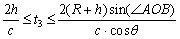 (8.9)
(8.9)
Coefficient 2 reflects the propagation delay of the signal on the upstream and downstream sections of the route.
The geostationary satellite is at a high altitude, from which more than a quarter of the surface of the globe is visible. This is one of the advantages of the geostationary orbit. Since the geostationary satellite seems to be stationary for an earth observer, it becomes easier to position the antennas of ground stations (tracking of the satellite’s position in orbit is not required). But the large height of the orbit has disadvantages: the signal propagation delay is about 1/4 of a second, the signal receives significant attenuation on such long paths. In addition, in the northern latitudes, the satellite is visible at small angles to the horizon, and in polar regions it is not at all visible. There are several hundred satellites in geostationary orbit, serving different regions of the Earth, including the domestic satellites Horizon and Ekran.
To service the territories in the northern latitudes, satellites in a high elliptical orbit with a large inclination angle are used. In particular, the domestic Molniya satellites have an elliptical orbit with a height of apogee over the northern hemisphere of about 40 thousand kilometers and a perigee of about 500 kilometers. The inclination of the plane of the orbit to the plane of the Earth's equator is 63 ° and the orbital period of 12 hours. The satellite movement in the apogee area slows down, and radio communication sessions are possible for 6 ... 8 hours. This type of satellite also allows you to serve large areas. But the disadvantage of their use is the necessity of tracking the antenna systems for slow-drifting satellites and their reorientation from the approaching satellite to the ascending one.
Low-orbiting satellites are launched into circular orbits with an altitude of about 500 ... 1500 kilometers and a large orbit inclination angle (polar and near-polar orbits). Start light communication satellites carried out using low-cost launchers. In communication systems with low-altitude satellites, the signal propagation delay times are small, but the coverage area is also significantly reduced. The speed of a satellite moving relative to the Earth’s surface is rather high, and the duration of a communication session from the satellite’s rising to its approach does not exceed tens of minutes. Therefore, to ensure communication in large areas in low-altitude orbits must be at the same time dozens of satellites.
In satellite communications systems (CAS), radio communication is usually maintained between several earth stations. Earth stations are connected to the sources and consumers of television and radio broadcasting programs, to the switching nodes of communication networks, for example, long-distance telephone exchanges. For example, consider the duplex communication option between two earth stations. The structural diagram of such an CCC is shown in Figure 8.9.
The signal U1, intended for transmission in the communication system, arrives at the transmitter PD1 of the first earth station. The transmitter Pd1 carries out the necessary transformations of the carrier collar with a frequency f1 (modulation, amplification, etc.) and the radio signal generated by the transmitter goes through the RF1 splitter filter to the antenna of the earth station 1, which emits it to the side of the repeater satellite. The U2 signal, which arrives for transmission in the communication system to the second earth station, undergoes similar transformations in similar nodes and is radiated towards the space station with a frequency equal to f2.
Radio signals with frequencies f1 and f2, induced in the antenna of the space station, through RF separation filter 0 are fed to the PM01 and PM02 signal receivers. The received signals receive the necessary processing in these receivers (frequency conversion, gain, in some communication systems, demodulation of signals or other transformations provided by the signal processing algorithm) are provided. Then, in the transmitters PD01 and PD02, the signals are transferred to the frequencies of the downlink signals and amplified to the required level. As a result of these transformations, the signal with frequency f1 at the output of the chain consisting of receiver PM01 and transmitter PD01 is converted into a signal with frequency f3, and the signal with frequency f3 at the output of chain PM02 - PD02 is converted into a signal with frequency f4. Through the RF0 separation filter, these signals arrive at the antenna of the space station and are radiated towards the earth stations.
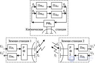
Fig. 8.9 Structural diagram of satellite communication system
On Earth, signals with frequencies f3 and f4 reach the antennas of earth stations and arrive at the inputs of the corresponding receivers. The PM2 receiver is tuned to the frequency f3, respectively, the U1 signal will be restored at the receiver output, fed to the input of the communication system from the earth station 1. In turn, the U1 signal transmitted by the earth station 2 will be restored at the PM1 receiver output.
For satellite communication systems, frequency bands are allocated separately for uplink and downlink channels in the frequency range from 0.6 ... 86 GHz.
In 1945, in an article called Extra-terrestrial Relays, published in the October issue of Wireless World magazine, English scientist, writer and inventor Arthur Clarke proposed the idea of creating a system of communication satellites in geostationary orbits that would allow organizing global communication system.
Subsequently, Clark answered the question why he did not patent the invention (which was quite possible) and answered that he did not believe in the possibility of implementing such a system in his lifetime, and also believed that such an idea should benefit all of humanity.
The first studies in the field of civil satellite communications in Western countries began to appear in the second half of the 50s of the 20th century. In the US, they were driven by the increased demand for transatlantic telephony.
In 1957 in the USSR the first artificial satellite of the Earth was launched with radio equipment on board.
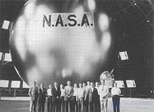
On August 12, 1960, US specialists launched an inflatable balloon into an orbit of 1,500 km [1] . This spacecraft was called the "Echo-1". Its metallized shell with a diameter of 30 m served as a passive repeater.
On August 20, 1964, 11 countries (the USSR did not enter their number) signed an agreement on the creation of the international satellite communications organization Intelsat (International Telecommunications Satellite Organization) [2] . By that time, the USSR had its own advanced satellite communications program, which was crowned on April 23, 1965 with the successful launch of the connected Soviet satellite Molniya-1. As part of the Intelsat program, the first commercial communication satellite Early Bird (Eng.) (“Early Bird”) [3] , produced by COMSAT, was launched on April 6, 1965.
By today's standards, the Early Bird satellite ( INTELSAT I ) had more than modest capabilities: having a bandwidth of 50 MHz, it could provide up to 240 telephone communication channels [4] . At any given time, communication could occur between an earth station in the United States and only one of the three earth stations in Europe (in the United Kingdom, France or Germany) that were interconnected by cable lines [5] .
In the future, the technology stepped forward, and the INTELSAT IX satellite already had a bandwidth of 3456 MHz [4] .
For a long time, satellite communications in the USSR developed only in the interests of the USSR Ministry of Defense. Due to the greater closeness of the space program, the development of satellite communications in socialist countries was different than in Western countries. The development of civil satellite communications began with an agreement between 9 countries of the socialist bloc on the creation of the Intersputnik communication system, which was signed only in 1971. [6]
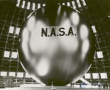
In the early years of research, passive satellite repeaters (examples — the Echo and Echo-2 satellites) were used, which were a simple radio signal reflector (often a metal or polymer sphere with a metal coating) that did not carry any transmitting equipment on board . Such satellites are not spread. All modern communications satellites are active. Active repeaters are equipped with electronic equipment for receiving, processing, amplifying and relaying a signal.
Satellite repeaters can be non-regenerative and regenerative [7] . A non-regenerative satellite, having received a signal from one earth station, transfers it to another frequency, amplifies and transmits to another earth station. A satellite can use several independent channels that carry out these operations, each of which works with a certain part of the spectrum (these processing channels are called transponders [8] ).
The regenerative satellite demodulates the received signal and re-modulates it. Due to this, error correction is performed twice: at the satellite and at the receiving earth station. The disadvantage of this method is the complexity (and therefore a much higher cost of the satellite), as well as the increased signal transmission delay.
The orbits on which satellite transponders are placed are divided into three classes [9] :
An important kind of equatorial orbit is the geostationary orbit, in which the satellite rotates with an angular velocity equal to the angular velocity of the Earth, in the direction coinciding with the direction of rotation of the Earth. The obvious advantage of the geostationary orbit is that the receiver in the service area "sees" the satellite constantly.
However, the geostationary orbit is one, its capacity, determined by the length of the circumference of the orbit divided by the size of the satellites, taking into account the "safety intervals" between them, is finite. Therefore, all the satellites that I would like to display on it is impossible [ source not specified 549 days ] . Its other drawback is the high altitude (35,786 km), which means the higher cost of launching a satellite into orbit. In addition, the power flux density at the earth’s surface at the signal receiving point decreases from the equator to the poles due to the smaller angle of inclination of the vector of electromagnetic energy to the earth’s surface, as well as due to the increasing signal path through the atmosphere and associated absorption. Therefore, a satellite in geostationary orbit is practically incapable of servicing earth stations in the polar regions.
Oblique orbit allows to solve these problems, however, due to the movement of the satellite relative to the ground observer, it is necessary to launch at least three satellites into one orbit in order to provide round-the-clock access to communication.
The polar orbit is an extreme case of an oblique (with a 90º inclination).
When using oblique orbits, earth stations are equipped with tracking systems that guide the antenna to the satellite [10] . Stations operating with satellites in the geostationary orbit, as a rule, are also equipped with such systems to compensate for the deviation from the ideal geostationary orbit. An exception is made by small antennas used for receiving satellite television: their radiation pattern is quite wide, so they do not feel a lot of *** satellites near an ideal point.
Since the radio frequency range is a limited resource, it is necessary to ensure that the same frequencies can be used by different earth stations. This can be done in two ways [11] :
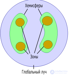
A typical coverage map for a satellite in geostationary orbit includes the following components [12] :
Moreover, all frequencies (with the exception of those reserved for the global beam) are used repeatedly: in the western and eastern hemispheres and in each of the zones.
The choice of frequency for data transmission from the earth station to the satellite and from the satellite to the earth station is not arbitrary. The frequency depends, for example, on the absorption of radio waves in the atmosphere, as well as the necessary dimensions of the transmitting and receiving antennas. The frequencies at which the transmission from the earth station to the satellite occurs differ from the frequencies used for transmission from the satellite to the earth station (as a rule, the first are higher).
Frequencies used in satellite communications are divided into ranges denoted by letters. Unfortunately, in various literatures the exact range boundaries may not coincide. Indicative values are given in recommendation ITU-R V.431-6 [13] :
| Range name | Frequencies (according to ITU-R V.431-6) | Application |
|---|---|---|
| L | 1.5 GHz | Mobile satellite communications |
| S | 2.5 GHz | Mobile satellite communications |
| WITH | 4 GHz, 6 GHz | Fixed satellite communications |
| X | For satellite communications, the ITU-R recommendations are not defined. For radar applications, the range is 8-12 GHz. | Fixed satellite communications |
| Ku | 11 GHz, 12 GHz, 14 GHz | Fixed satellite communications, satellite broadcasting |
| K | 20 GHz | Fixed satellite communications, satellite broadcasting |
| Ka | 30 GHz | Fixed satellite communications, inter-satellite communications |
Higher frequencies are also used, but their increase is hindered by the high absorption of radio waves of these frequencies by the atmosphere. Ku-диапазон позволяет производить прием сравнительно небольшими антеннами, и поэтому используется вспутниковом телевидении (DVB), несмотря на то, что в этом диапазоне погодные условия оказывают существенное влияние на качество передачи.
Для передачи данных крупными пользователями (организациями) часто применяется C-диапазон. Это обеспечивает более высокое качество приема, но требует довольно больших размеров антенны.
Особенностью спутниковых систем связи является необходимость работать в условиях сравнительно низкого отношения сигнал/шум, вызванного несколькими факторами:
В связи с этим спутниковая связь плохо подходит для передачи аналоговых сигналов. Поэтому для передачи речи её предварительно оцифровывают, используя, например, импульсно-кодовую модуляцию (ИКМ) [14] .
Для передачи цифровых данных по спутниковому каналу связи они должны быть сначала преобразованы в радиосигнал, занимающий определённый частотный диапазон. Для этого применяется модуляция (цифровая модуляция называется также манипуляцией ). Наиболее распространёнными видами цифровой модуляции для приложений спутниковой связи являются фазовая манипуляция и квадратурная амплитудная модуляция [15] . Например, в системах стандарта DVB-S2 применяются QPSK, 8-PSK, 16-APSK и 32-APSK [16] .
Модуляция производится на земной станции. Модулированный сигнал усиливается, переносится на нужную частоту и поступает на передающую антенну. Спутник принимает сигнал, усиливает, иногда регенерирует, переносит на другую частоту и с помощью определённой передающей антенны транслирует на землю.
Из-за низкой мощности сигнала возникает необходимость в системах исправления ошибок. Для этого применяются различные схемы помехоустойчивого кодирования, чаще всего различные варианты свёрточных кодов (иногда в сочетании с кодами Рида-Соломона), а также турбо-коды [17] [18] и LDPC-коды [19] .
Для обеспечения возможности одновременного использования спутникового ретранслятора несколькими пользователями применяют системы множественного доступа [20] :
Кроме того, многим пользователям не требуется постоянный доступ к спутниковой связи. Этим пользователям канал связи (таймслот) выделяется по требованию с помощью технологии DAMA (Demand Assigned Multiple Access — множественный доступ с предоставлением каналов по требованию).
Изначально возникновение спутниковой связи было продиктовано потребностями передачи больших объёмов информации. Первой системой спутниковой связи стала система Intelsat, затем были созданы аналогичные региональные организации (Eutelsat, Arabsat и другие). С течением времени доля передачи речи в общем объёме магистрального трафика постоянно снижалась, уступая место передаче данных.
С развитием волоконно-оптических сетей последние начали вытеснять спутниковую связь с рынка магистральной связи [21] .
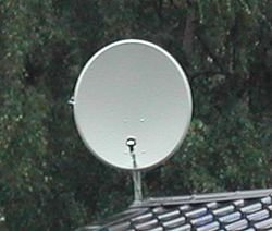
Системы VSAT (Very Small Aperture Terminal — терминал с очень маленькой апертурой) предоставляют услуги спутниковой связи клиентам (как правило, небольшим организациям), которым не требуется высокая пропускная способность канала. Скорость передачи данных для VSAT-терминала обычно не превышает 2048 кбит/с [22] .
Слова «очень маленькая апертура» относятся к размерам антенн терминалов по сравнению с размерами более старых антенн магистральных систем связи. VSAT-терминалы, работающие в C-диапазоне, обычно используют антенны диаметром 1,8-2,4 м, в Ku-диапазоне — 0,75-1,8 м.
В системах VSAT применяется технология предоставления каналов по требованию.
Особенностью большинства систем подвижной спутниковой связи является маленький размер антенны терминала, что затрудняет прием сигнала. Для того, чтобы мощность сигнала, достигающего приёмника, была достаточной, применяют одно из двух решений:
С операторами персональной спутниковой связи конкурируют операторы сотовой связи. Характерно, что как Globalstar, так и Iridium испытывали серьёзные финансовые затруднения, которые довели Iridium до реорганизационного банкротства в 1999 г.
В декабре 2006 года был запущен экспериментальный геостационарный спутник Кику-8 с рекордно большой площадью антенны, который предполагается использовать для отработки технологии работы спутниковой связи с мобильными устройствами, не превышающими по размерам сотовые телефоны.
Спутниковая связь находит применение в организации «последней мили» (канала связи между интернет-провайдером и клиентом), особенно в местах со слабо развитой инфраструктурой. [24]
Особенностями такого вида доступа являются:
По типу исходящего канала различают:
И в том, и в другом случае данные от провайдера к клиенту передаются, как правило, в соответствии со стандартом цифрового вещания DVB, что позволяет использовать одно и то же оборудование как для доступа в сеть, так и для приема спутникового телевидения.
Огромные расстояния между земными станциями и спутником являются причиной того, что отношение сигнал/шум на приёмнике очень невелико (гораздо меньше, чем для большинства радиорелейных линий связи). Для того, чтобы в этих условиях обеспечить приемлемую вероятность ошибки, приходится использовать большиеантенны, малошумящие элементы и сложные помехоустойчивые коды. Особенно остро эта проблема стоит в системах подвижной связи, так как в них есть ограничение на размер антенны и, как правило, на мощность передатчика.
На качество спутниковой связи оказывают сильное влияние эффекты в тропосфере и ионосфере [25] .
Степень поглощения сигнала атмосферой находится в зависимости от его частоты. Максимумы поглощения приходятся на 22,3 ГГц (резонанс водяных паров) и 60 ГГц (резонанс кислорода) [26] . В целом, поглощение существенно сказывается на распространении сигналов с частотой выше 10 ГГц (то есть, начиная с Ku-диапазона). Кроме поглощения, при распространении радиоволн в атмосфере присутствует эффект замирания, причиной которому является разница в коэффициентах преломленияразличных слоёв атмосферы.
Эффекты в ионосфере обусловлены флуктуациями распределения свободных электронов. К ионосферным эффектам, влияющим на распространение радиоволн, относят мерцание , поглощение , задержку распространения , дисперсию , изменение частоты , вращение плоскости поляризации [27] . Все эти эффекты ослаб***яются с увеличением частоты. Для сигналов с частотами, большими 10 ГГц, их влияние невелико. [28]
| Эффект | 100 МГц | 300 МГц | 1 ГГц | 3 ГГц | 10 ГГц |
|---|---|---|---|---|---|
| Вращение плоскости поляризации | 30 оборотов | 3,3 оборота | 108° | 12 ° | 1,1° |
| Дополнительная задержка сигнала | 25 мс | 2,8 мс | 0.25 ms | 28 ns | 2.5 ns |
| Absorption in the ionosphere (at the pole) | 5 dB | 1.1 dB | 0.05 dB | 0.006 dB | 0.0005 dB |
| Absorption in the ionosphere (in mid-latitudes) | <1 dB | 0.1 dB | <0.01 dB | <0.001 dB | <0.0001 dB |
Signals with a relatively low frequency (L-band and partially C-band) suffer from ionospheric scintillation due to irregularities in the ionosphere. The result of this flicker is a constantly varying signal strength.
The problem of the propagation delay somehow affects all satellite communication systems. Systems using a satellite repeater in a geostationary orbit have the greatest delay. In this case, the delay due to the finite speed of propagation of radio waves is approximately 250 ms, and taking into account multiplexing, switching, and signal processing delays, the total delay can be up to 400 ms [29] .
The propagation delay is most undesirable in real-time applications, such as telephony. At the same time, if the propagation time of a signal over a satellite communication channel is 250 ms, the time difference between the replicas of subscribers cannot be less than 500 ms.
In some systems (for example, in VSAT systems using the star topology), the signal is transmitted twice through a satellite communication channel (from the terminal to the central node, and from the central node to another terminal). In this case, the total delay is doubled.
When the Sun approaches the axis of the satellite-ground station, the radio signal received from the satellite by the ground station is distorted as a result of interference.

Comments
To leave a comment
Devices for the reception and processing of radio signals, Transmission, reception and processing of signals
Terms: Devices for the reception and processing of radio signals, Transmission, reception and processing of signals