Lecture
To the local oscillators of modern radio receivers, at present, there are requirements to ensure frequency stability such as only quartz oscillators can provide. At the same time, they should provide restructuring from one frequency to another. These requirements can be combined only in special devices - frequency synthesizers.
Frequency synthesizers, used as the local oscillators of radio receivers, are currently mainly implemented using a phase automatic frequency control (PLL) circuit. This is due to the fact that the range of adjustment of the local oscillators in the receivers of the VHF mobile communication range is quite small.
Consider the main blocks included in the block diagram of phase automatic frequency control (PLL). A block diagram of the PLL is shown in Figure 1.
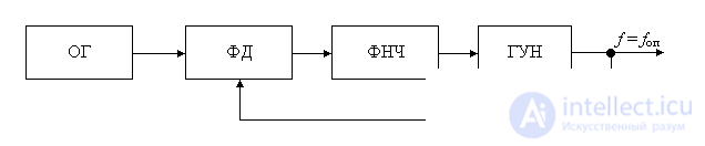
Figure 1. Block diagram of the phase locked loop (frequency synthesizer) circuit
The structure of this block diagram includes a phase detector (PD), which forms the error signal of the generated oscillation. The output oscillation is generated by a voltage controlled oscillator (VCO). The exemplary oscillation in this circuit forms the reference oscillator (OG). Another integral link in the phase-locked loop is the low-pass filter (LPF), which avoids self-excitation of the entire circuit.
Depending on the elements used in the phase-locked loop, it can be analog (when using analog phase detector circuits), digital (when using logic circuits as the phase detector), and fully digital (when implementing a low-pass filter in digital form).
As a result of the operation of the circuit shown in Figure 1, in the ideal case we can get exactly the same oscillation as the oscillation of the reference oscillator. But then why the whole scheme? After all, one could simply take the signal from the output of the reference generator.
The first task that can be solved using the phase automatic frequency control scheme is the implementation of the detection of a frequency-modulated signal. If you remove the voltage from the output of the low-pass filter, which is part of the phase-locked loop, its level will be proportional to the deviation of the frequency of the reference generator from the nominal value.
However, we were going to use the PLL to generate a given set of frequencies. That is, we need to learn how to change the frequency of the voltage controlled oscillator. To do this, turn on the frequency divider in the feedback circuit, as shown in Fig. 2. The frequency of the signal at the output of this divider will decrease compared to the input value by a factor of 1. But after all, at the input of the phase detector, the frequencies must be equal to each other. To do this, we will increase the frequency of the VCO division factor times. If an attempt is made to change the VCO frequency relative to this value, the phase-locked loop will return it to its nominal value.
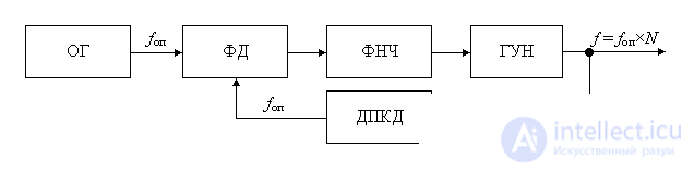
Figure 2. Block diagram of a digital frequency synthesizer
In the block diagram shown in Figure 2, a divider with a variable division factor (DFD) is used. By changing the division ratio N of the PDKD divider, you can tune the output frequency of the generator. In this scheme, both a digital phase detector and a phase comparator can be used as a phase detector. The use of a phase comparator allows you to extend the frequency range of the loop capture phase automatic frequency control of the frequency synthesizer.
As we already know from the course of digital circuitry, the division ratio of a digital frequency divider can reach several thousand. By choosing a sufficiently low reference frequency f op, you can get a synthesizer tuning step that satisfies the requirements for a tunable frequency generator. The pitch of the synthesizer in the PLL is obtained equal to the frequency of the reference oscillator.
Usually in radio engineering circuits a small step is required to reorganize the generator. The magnitude of this step is hundreds of hertz, or, in extreme cases, units of kilohertz. In mobile radio systems, the frequency synthesizer tuning step should be equal to the width of the communication channel. As a result, a new problem arises. We cannot use a crystal oscillator to form such a frequency, because quartz resonators that are acceptable in size and cost can only operate in the frequency range from 1 to 30 MHz.
However, to obtain a low comparison frequency at the inputs of the phase detector, at the output of the reference oscillator you can put another digital frequency divider with a constant division factor, as done in the scheme shown in Figure 3. In this scheme we can choose the comparison frequency values f cf, the reference frequency f op and the output oscillation f in a fairly wide range.
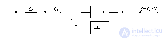
Figure 3. Block diagram of a digital frequency synthesizer with a small frequency tuning step
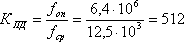
As an example, let's define the requirements for the blocks included in the block diagram of a synthesizer that produces frequencies in the range from 146 to 174 MHz. Let the reference frequency generator 6.4 MHz be used in the circuit. Such highly stable generators are offered by many companies as ready-made modules, for example, a 6.4 MHz CFPT-9006-FC-1B module from C-MAC.
The frequency tuning step in a given frequency range is determined by the frequency separation of the radio channels by frequency (channel width). At present, in this frequency range, the CCIR recommends building equipment with a radio channel bandwidth of 12.5 kHz. Let our frequency synthesizer have exactly this frequency tuning step. Then the comparison frequency at the input of the phase detector should also correspond to this value. From here you can determine the division ratio of the constant divisor PD:
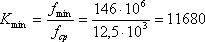
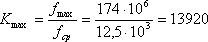
Now we define the maximum and minimum values of the division coefficients DPDC:
All obtained division factors are easily implemented by one of the frequency divider schemes (digital counters), which we considered in previous chapters. Now you can begin to develop the concept of the synthesizer. The only block that was not considered in previous chapters was the block for determining the error in frequency. Let us dwell on this block in more detail.

Comments